
Arm Base Assembly Guide v2.1
Arm Base Assembly Guide v2.1
Updated December 2014
This guide shows how to assemble the arm base with either the SSC-32 or the SSC-32U servo controller. Take note of which you have and follow each step accordingly, as the connections and configuration are different.
Safety first! Wear eye protection and never touch a powered robot!
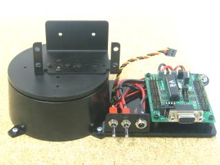
Arm Base mounted (SSC-32 shown).
Insert the stainless steel pins into the plastic bearings as shown.
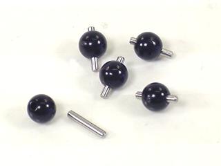 Figure 1.
Install the bearings into the base as shown — they will fit snugly. Note: the notch in the bottom edge of the base indicates the back.
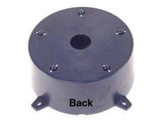 Figure 2.
Lay a piece of 400 grit sandpaper on a flat surface and move the base (upside down) in small circles on it. This will remove any imperfections on the bearings.
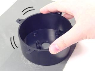 Figure 3.
Figure 4 shows the circle pattern on the sandpaper. The inset shows the bearings after any imperfections have been removed.
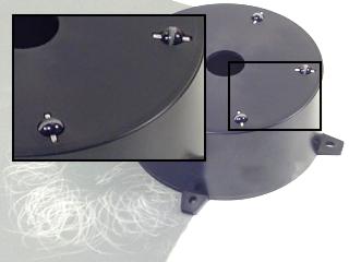 Figure 4.
Verify that the servo output horn is at center position as shown. Carefully remove the servo horn screw and pull the horn straight off. Refer to Table 5 for the correct servo for your kit.
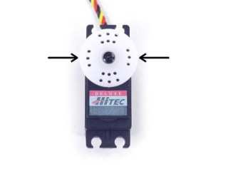 Figure 5.
Base Servo by Kit (Table 5)
| Kit | Servo |
|---|---|
| AL5A | HS-422 or HS-425 |
| AL5B, D | HS-485 |
Place the servo in the base as shown and screw it in tightly using four #4 tapping screws.

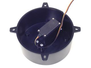 Figure 6.
AL5A / AL5B — Step 7a
Attach the ASB-201 bracket onto the base top using four 2-56 x .250" Phillips screws and four 2-56 nuts. The bracket and hardware are included in the arm kit, not the base kit. DO NOT USE LOCTITE ON PLASTIC.
AL5D — Step 7b
Attach the ASB-204 bracket onto the base top using four 2-56 x .250" Phillips screws and four 2-56 nuts. DO NOT USE LOCTITE ON PLASTIC.
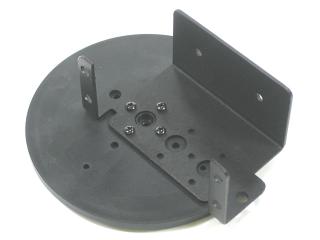 Figure 7a (ASB-201).
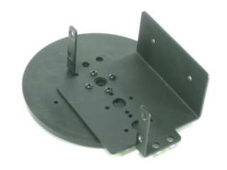 Figure 7b (ASB-204).
Add a drop of silicone-based oil to each bearing.
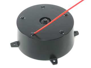 Figure 8.
Install the base top. The hole pattern should line up as shown in Figure 9, with one line pointing to the servo wire hole and all lines pointing between the mounting tabs. This top piece is manufactured to be a tight fit — you may have to press very hard. Attach the top with the servo horn screw.
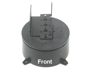 Figure 9.
Route the base servo's cable through the hole in the back of the base. This will keep the base level to the mounting surface.
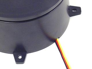 Figure 10.
Attach the 3/8" hex spacers as shown using four 1/4" hex socket screws.
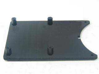 Figure 11.
Install the power switch bracket using two 3/8" hex socket screws and two nylon insert lock nuts.

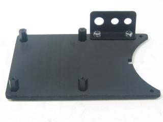 Figure 12.
Install the power plug wiring harness as shown and use a wire tie to hold the wires in place.
Before connecting to the SSC-32, verify the harness polarity: put the black voltmeter lead on the black wire and the red lead on the red wire. Plug the wall pack in, turn on the switch. The voltmeter should read approximately +6VDC. If it reads -6VDC, do NOT connect to the SSC-32 and contact support.
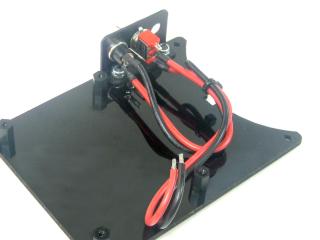 Figure 13.
SSC-32 (Serial) — Step 14a
The SSC-32 may require a 9V power source for the logic. Install the 9VDC battery wiring harness as shown. This is needed only for the older SSC-32 — not the SSC-32U.
SSC-32U (USB) — Step 14b
The SSC-32U does not need a separate logic power source. No 9V harness is included — proceed to the next step.
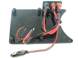 Figure 14a (SSC-32).
Figure 14b (SSC-32U).
Figure 14a (SSC-32).
Figure 14b (SSC-32U).
Install the SSC-32 or SSC-32U using four 1/4" hex socket screws. Do not make the electrical connections yet.
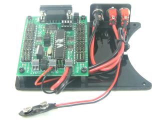 Figure 15 (SSC-32).
SSC-32 (Serial) — Step 16a
Attach the 9V DC wires to the VL input and the power plug wires to the VS1 input. Black to (−), red to (+). Remove the VL=VS1 jumper to isolate servo power from logic power and prevent brownouts. Ensure no loose strands cause a short.
SSC-32U (USB) — Step 16b
Insert the power plug wires into the VS1 input. Black to (−), red to (+). Leave the VS1=VS2 jumpers in place. There should be no jumper on VS=VL. Tighten screws firmly and check for no loose strands.
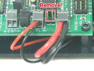 Figure 16a (SSC-32).
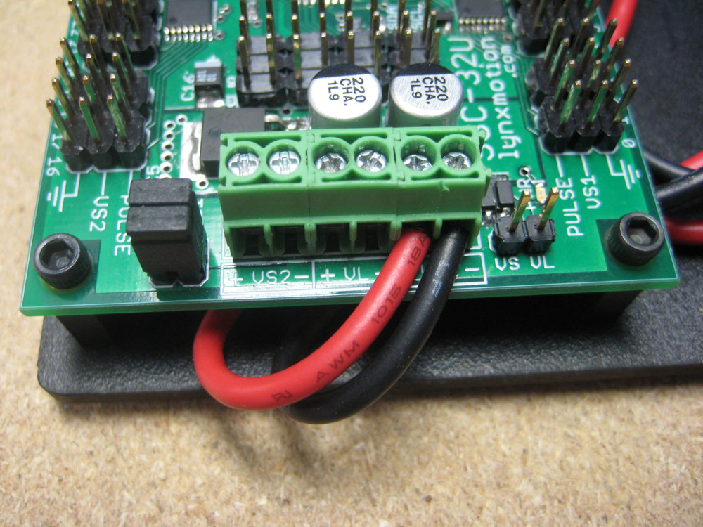 Figure 16b (SSC-32U).
Mount everything to a piece of plywood or similar surface. Attach the electronics carrier as shown. Route the base servo wire through the holes and verify it isn't being pinched. Use four #4 x .500" tapping screws to secure the assembly to the plywood.
 Figure 17a (SSC-32).
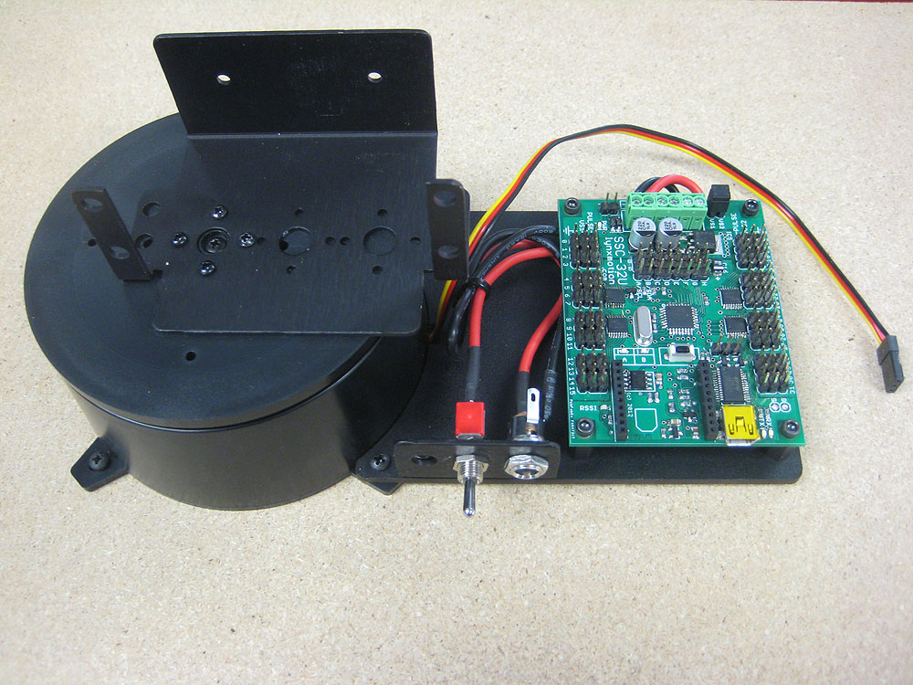 Figure 17b (SSC-32U).
Plug the base rotate servo into channel 0 on the SSC-32 or SSC-32U as shown. The black wire goes closest to the outside of the board; the yellow wire goes to the inside (the "pulse").
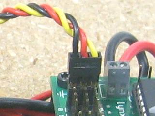 Figure 18a (SSC-32).
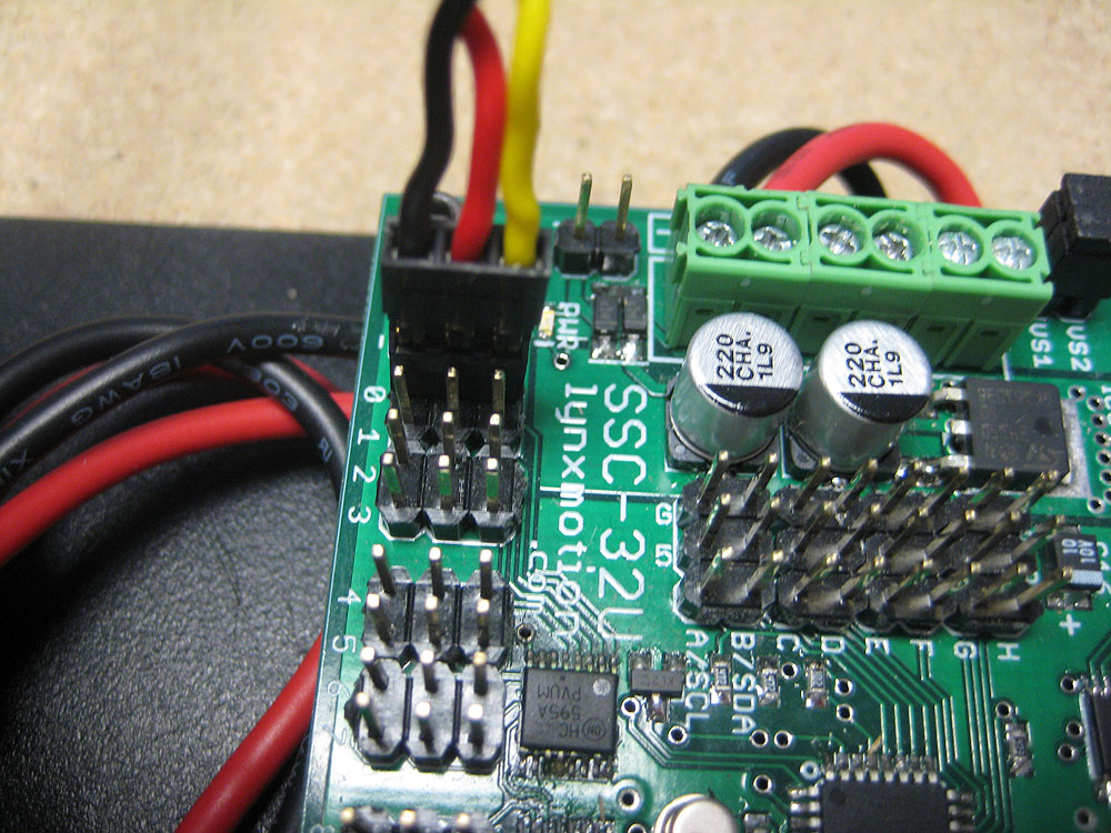 Figure 18b (SSC-32U).
SSC-32 (Serial) — Step 19a
Plug in the wall pack and DB9 data cable as shown. The wall adapter is universal (110V–220V) — if it doesn't have the right plug for your country, purchase an inexpensive plug adapter. Download and install LynxTerm. Connect the SSC-32 to the serial port and apply power. The green LED should light up.
SSC-32U (USB) — Step 19b
Plug in the wall pack and USB cable as shown. The wall adapter is universal (110V–220V).
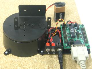 Figure 19a (SSC-32).
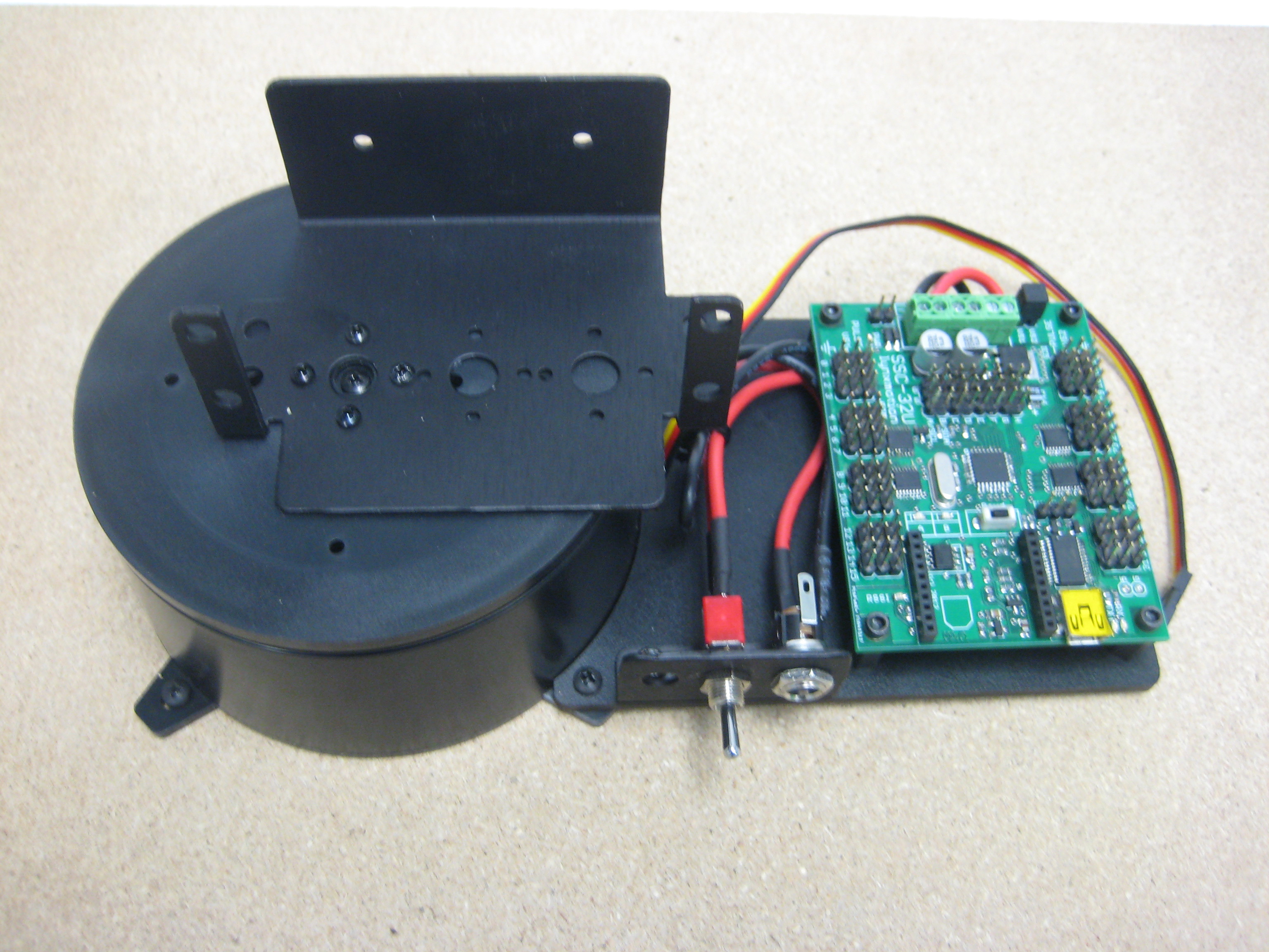 Figure 19b (SSC-32U).
SSC-32U (USB) — Step 20a
Download and install the SSC-32 Servo Sequencer Utility. Ensure the On/Off switch is on, the board is powered and connected via USB. Set baud rate to 9600. The software should auto-detect the COM port with FTDI drivers. Use the slider for servo 0 to verify the base servo moves. Turn off power, remove the power and USB cables, and continue with the next guide.
SSC-32 (Serial) — Step 20b
In LynxTerm, type "ver" and press Enter. You should see "SSC32-V2.01XE" or higher. Consult the serial troubleshooting guide if needed. Select channel 0 and use the slider to rotate the base. Press "All=1500" to re-center before moving on. Turn off power, remove the power and serial cables, and continue with the next guide.
 Figure 20a (SSC-32 Servo Sequencer Utility).
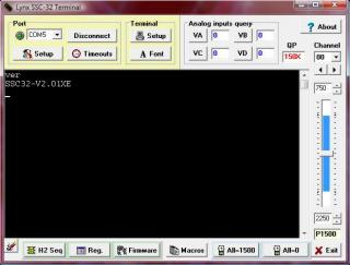 Figure 20b (LynxTerm).