02 - Conv. HD Structure

Last modified by Eric Nantel on 2023/02/21 11:00

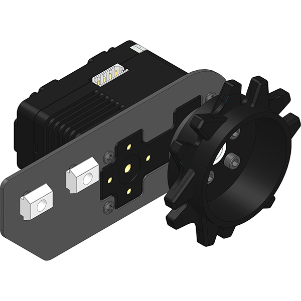
Structure - Assembly A
Step 1/5
Side Plates
Assembly C
Side Plates
Assembly E
1x AE-20-500
500mm Extrusion
Comments:It's important to align the end of the T-Nuts with the aluminum extrusion. This will provide the right tension on the track later on.

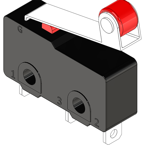
Limit Switch for Gear Motor
Optional
1x Switch
Generic Switch
2x PHS-05
2-56 x 1/2
2x SLN-04
2-56 Nylock

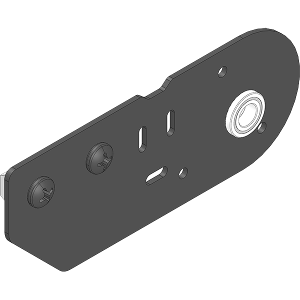
Structure - Assembly B
Step 2/5
1x SPRK-01
Small Sprocket
1x HUB-02
Sprocket Adapter
4x SHS-01
4-40 x 1/4"

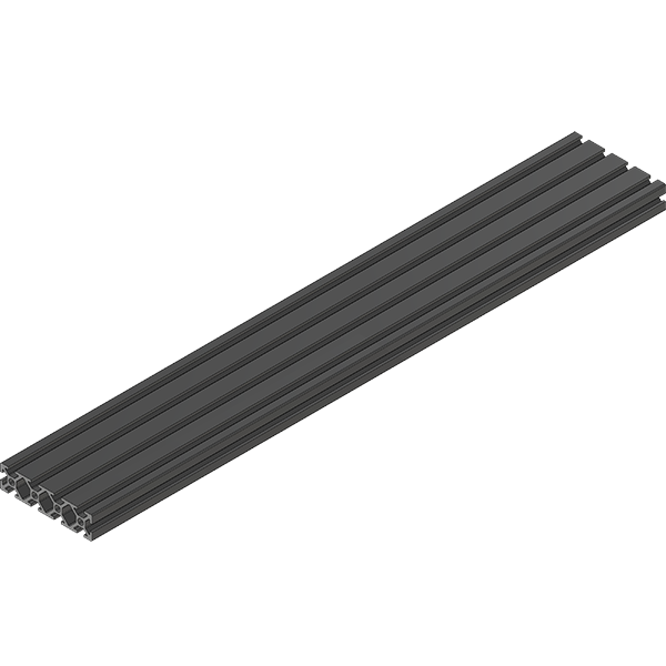
Structure - Assembly C
Step 3/5
Structure
Assembly B
1x KNB-01
Knob Wheel
1x SHF-01
6mm x 90mm Shaft
2x CPS-02
10-32 x 1/4"
1x SHS-04
4-40 x 1/2"
Comments:Setscrews should be tighten on the FLAT side of the shaft, this allign the sprockets.

Geared Motor Specific
Optional
Structure
Assembly B
1x KNB-01
Knob Wheel
1x SHF-01
6mm x 90mm Shaft
3x CPS-02
10-32 x 1/4"
Comments:Setscrews should be tighten on the FLAT side of the shaft, this allign the sprockets.

Structure - Assembly D
Step 4/6
Structure
Assembly C
Side Plates
Assembly D
Side Plates
Assembly E
4x TNUT-M4
M4 T-Nut
Comments:It's important to align the end of the T-Nuts with the aluminum extrusion. This will provide the right tension on the track later on.

Structure - Assembly E
Step 5/6
2x SPRK-01
Small Sprocket
2x HUB-02
Sprocket Adapter
8x SHS-01
4-40 x 1/4"
Comments:In this step you need to make two sprocket assembly, one of each alignment kind.

Structure - Assembly F
Step 6/6
Structure
Assembly E
1x SHF-01
6mm x 90mm Shaft
2x CPS-02
10-32 x 1/4"
Comments:Setscrews should be tighten on the FLAT side of the shaft, this allign the sprockets.

Tags:
Created by Eric Nantel on 2023/02/21 09:51
Copyright RobotShop 2018