
ses-v2-info (redirect)
Page Contents
Description
Lynxmotion's Servo Erector Set (S.E.S.) is a modular robotic construction system which allows a near infinite variety of different (and complex) robots and systems. Imagine your next robotic creation, get the parts you need to build it, and then control it! Lynxmotion's first Servo Erector Set came out in 2009 and a wide variety of different kits were created using the V1 system, including several robot arms, a variety of bipeds, a plethora of hexapods and more. The V2 system, released in 2019, is an evolution of the original SES V1 and was created with the following goals:
- Evolution and modernization of the SES V1 modular construction system
- Add advanced features while reducing mechanical complexity
- SES V1 compatibility (whenever possible)
- Compatibility with several 3rd party manufacturer products
- Improved documentation, design and packaging
Aside from the servos themselves, there are three main elements to the Servo Erector Set system:
SES - Electronics
The V1 system was based on the BotBoarduino Arduino-compatible microcontroller and the SSC-32U servo controller. A variety of servo cable extensions, wiring harnesses and related cabling was used to connect everything together. The V2 system focuses on smart servo cables while still permitting RC control. The main electronics for the V2 include only an adapter and power hub.
The SES V2 system is meant to be powered using either batteries or a wall adapter. When building a mobile robot, the suggested pack is the Lynxmotion 11.1V, 3500mAh Lithium Ion battery pack, which can be charged from most Li-Ion battery chargers via the four-pin charging connector. Alternatively, most 2S (7.4V) and 3S (11.1V) Lithium-based battery packs with XT60 connector can be used with the LSS Servos. The servos can be powered using as little as 6V, though if a battery pack selected drops below this value, the servos will cut.
When creating a stationary robot like a robotic arm, the suggested wall adapter is the Lynxmotion 12V, 6A wall adapter with XT60 connector. If a different wall adapter is selected which has a standard barrel connector, power can be supplied using the LSS Power Hub as intermediary, leaving the LSS Adapter's XT60 not connected. Note that the LSS Power Hub cannot provide ~3A to all servos in the bug whereas the LSS Adapter is designed to handle servos connected to a bus.
Go to SES - Electronics
SES - Mechanics
The Lynxmotion Servo Erector Set has always included both metric and imperial dimensions, and the V1 system used almost 150 different screws, nuts, washers, standoffs and related accessories. The V2 reduces this down to less than 10, focusing 2-56 threaded pan head screws and 2-56 nuts for bracket connections, and M3 screws for standoffs and servo horn mounting.
The first SES system used a variety of different Hitec RC servos, and brackets were designed to adapt these servos to to the Erector Set. Although a standard RC servo case size existed for many Hitec servos, several series of brackets had to be created to accommodate different servo sizes (micro, standard and large). Some brackets were designed to have one specific application (for example the body panels for a specific hexapod design) while most were meant to be as modular as possible. In all around 70 brackets were created for the V1 SES system. Disregarding the Hitec RC servo-specific brackets, the remaining brackets from the V1 can mostly be used for the V2 system. The new Lynxmotion Smart Servos were designed to be used with the v1 bracket system in order to create a modular robotic building system called the Lynxmotion Servo Erector Set (S.E.S.) v2. It is therefore entirely possible to create a new robot which uses elements from both the V1 and V2 systems. The SES V1 provided an option for 1:1 external gearing, and the V2 system also includes the option for adding external gears (1:1 and 1:3) which can be mounted to the servo itself as well as using an external gearbox bracket. Gears use a standard pitch of 16, allowing them to be compatible with other spur gears and gear racks of the same pitch.
Go to SES - Mechanics
SES - Software
There is a variety of software available for the erector set V1 (SSC-32 and SSC-32U RC servo controllers) and V2 (smart servos). Software for the v1 (not including legacy software) include FlowBotics Studio (and a variety of Windows-compatible apps), FlowArm PLTW, the SSC-32 servo sequencer.
Software for the V2 includes the LSS Config, which is a tool to easily control, configure and update individual smart servos, a new version of FlowArm designed for using the smart servos, as well as libraries in Arduino, Python and ROS. Additional software to come.
Go to SES - Software
SES Mounting Pattern
The SES mounting pattern was based on two holes which are used for mounting objects to a Hitec standard servo horn such as the Hitec HS-422. The holes are meant for 2-56 (imperial) threaded screws. Screws which are 1/4 inch long are able to hold together two brackets with enough thread protruding to add a 2-56 nut. In most situations only two screws are needed, though four screws can be used. The mounting pattern has evolved to include three variations:
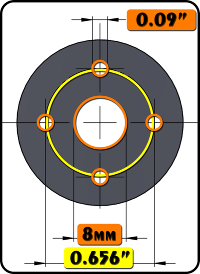 | SES V1 Pattern
|
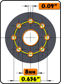 | SES V2 Pattern Newer brackets and parts have four additional holes (for a total of eight holes) spaced at 45 degrees to allow for easy mounting.
|
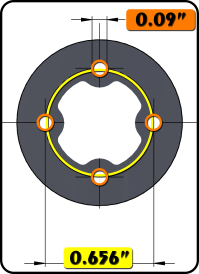 | SES V2b Pattern Several of the brackets have an opening which allows the SES V2 cable(s) to pass through. The aluminum clamping hub also has this opening, so when used with carbon fiber tubing, the wires can be passed within the structure.
|