BASIC Micro Studio Programming Tutorial for BASIC Atom Pro
| BASIC
Micro Studio Programming Tutorial for BASIC Atom Pro.
Updated 09/23/2009. Safety first! Wear eye protection and never touch a powered robot! Note: The purpose of this tutorial is to illustrate how to download a BASIC program onto the BASIC Atom Pro processor, and test the functionality of the Bot Board II. |
|||
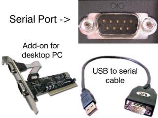
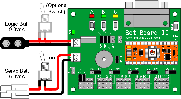
| Step 1. Install the Atom Pro module into the Bot Board II as shown in the diagram below. Connect the serial data cable to the PC's serial port. This can be recognized by having 9 pins that stick out. Connect the other end of the serial data cable to the Bot Board's DB9 port. See the troubleshooting guide for a list of tested USB-to-Serial adaptors. Please consult the serial troubleshooting guide if you have difficulties with this. |
|
||
| Note: This schematic shows the default wiring and jumper configuration; even though servos are not used in this tutorial. Check to make sure
your Bot Board II is set up as shown in the diagram. Connect a 9vdc battery to the Bot Board's VL terminal. The green LED should light up
steadily.
|
|||
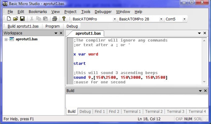
| Step 2. Download and install the latest version of the BASIC Micro Studio. Download the sample BASIC Atom Pro program, and save it on your computer, somewhere you will be able to easily find it. Open the IDE (double-click the desktop icon, or use the Start menu), then load up the sample program by clicking on File -> Open. |
|
||
| Step 3. Your screen should now look like Figure 2. Note that you can get more room for your programming window by turning off the "Workspace" window: either click the X at its top right corner, or from the View menu choose Toolbars, then uncheck the "Workspace" toolbar. The Build area (labeled "Build" at the bottom) shows error messages and compile time messages. You can optionally hide the Build window by clicking the X at its top right corner, or from the View -> Toolbars menu ("Results" toolbar). If you do hide it, make sure you unhide it again before compiling your program so you can see messages.
|
|||
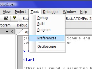
| Step 4. Now you need to change some options in order to connect with the Bot Board. Click on Tools -> Preferences. |
|
||
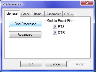
| Step 5. Click on "Find Processor". This will locate the COM port that the Bot Board is connected to, and automatically set the appropriate COM port and processor to default. Click "OK" to exit the Preferences screen. |
|
||
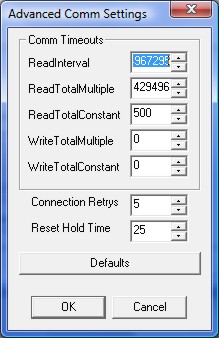
| Step 6. If you have trouble with the IDE not connecting with the Atom Pro, you may need to make an adjustment in the Advanced Comm Settings screen. Click on Tools -> Preferences -> Advanced. Adjust the "Reset Hold Time" a little at a time, until the IDE is able to connect. If you have no problems connecting, leave these settings alone. |
|
||
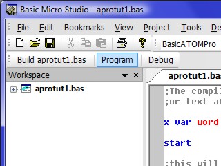
| Step 7. Click on the "Program" button located in the toolbar as shown. This will compile the program and load it onto the Atom Pro. The program will begin to run as soon as the Atom Pro receives it. |
|
||
| Step 8. Click on the "Terminal 1" tab at the bottom of the Output window, at the bottom of the screen. Make sure your settings are as shown in the figure below. Click the "Connect" button, and the results of the program (from the "serout" command) will display as shown.
|
|||
| Step 9. If you would like to fully test the Bot Board II and Atom Pro, download the Bot Board II testing program, and save it on your computer, somewhere you will be able to easily find it. Program the Atom Pro with this code. When the program is running, you can test the ABC buttons and LEDs. Pressing the A button will add one to a binary count that is visible on the LEDs. Pressing the B button will subtract one. The C button will clear the count. The speaker circuitry is tested by emitting a tone when the buttons are pressed. All of the I/O pins are toggled with each button press so you can read them with a volt meter. By clicking on the Terminal 1 tab, you can read the analog input on Pin 16 (AX0), which will reflect the VS value. You will need to change the Baud rate from 9600 to 57.6k in order to see these values. |
|||


