
A2WD1 SES Rover Assembly Guide v1.1
| 2WD
SES Rover Assembly Guide v1.1.
Updated May 2015 Safety first! Wear eye protection and never touch a powered robot! The purpose of this guide is to construct the 2WD chassis and install the electronics. The folllowing versions of the 2WD Rover are currently available:
To view larger images, right click on the image and click "view image". Steps 1 through 13 are the same for the BotBoarduino or the SSC-32 / 32U. Once you reach step 14, please follow whichever applies to the robot you are making. Note that we define the "front" of the robot as having the two driven wheels, and the rear associated with the single tail wheel. However, you are free to change this as you wish (it's mainly aesthetic), though note that the sample code may have them reversed. |
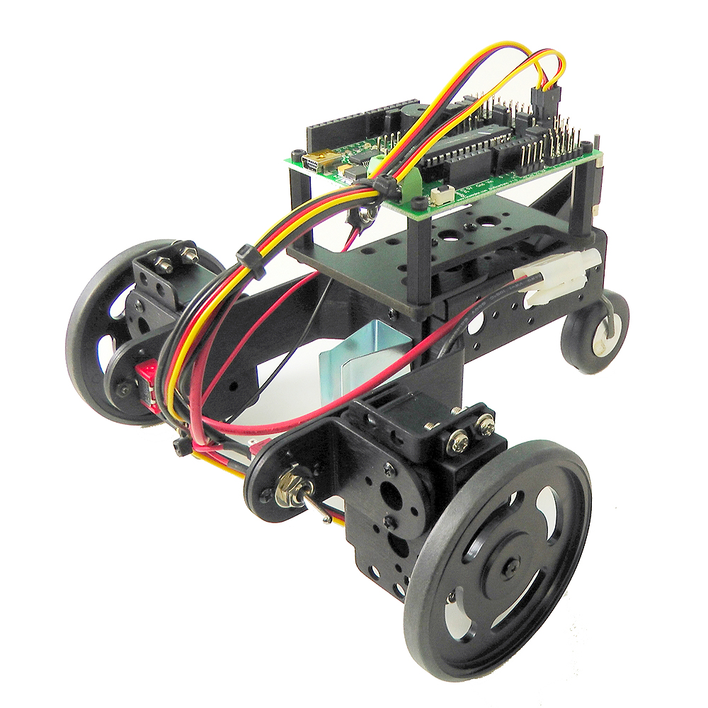 Finished 2WD SES Rover |
||||
| Step
1. Connect the plastic tail wheel support to the aluminum C-channel using a pair of 2-56 screws and nuts.
|
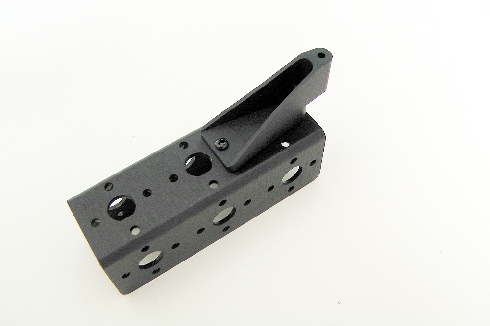 Figure 1. |
||||
| Step
2. Create a new sub-assembly using the large ASB-203 C-shaped bracket, the ASB-06 L-shaped bracket and the 9V battery hoolder. The 2-56 screw goes through the battery holder, then the L-bracket and finally through the C-channel. Note: The 9V battery is only used with the SSC-32 servo controller. The BotBoarduino's onboard regulator allows you to connect only the 6V battery, you can use it to power both VL and VS.
|
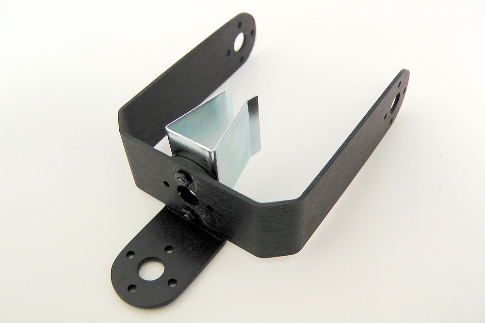 Figure 2. |
||||
| Step
3. Connect the two sub-assemblies as shown using a pair of 2-56 screws and a pair of (small) 2-56 hex spacers. The screws pass through the C-channel, then the L-bracket and finally into the threaded hex spacers.
|
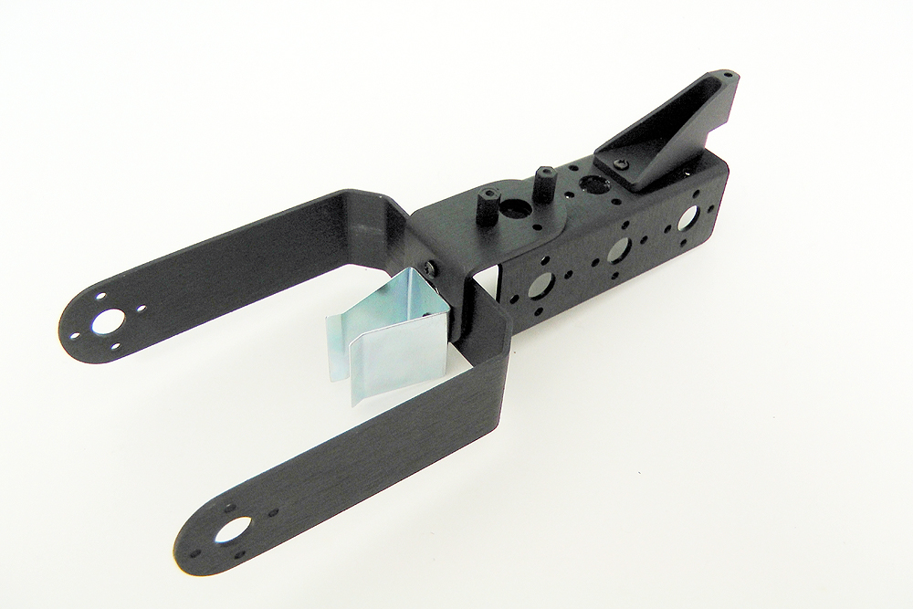 Figure 3. |
||||
| Step
4. Connect one L-bracket to either side of the C-bracket. Ensure the shorter side connects to the bracket.
|
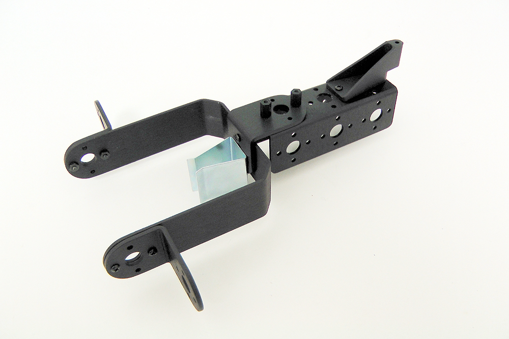 Figure 4. |
||||
| Step
5. Connect one ASB-04 multi-purpose servo bracket to each of the L-brackets as shown. Use two 2-56 screws and two 2-56 nuts for each bracket (for a total of 4x 2-56 nuts and 4x 2-56 screws for this step..
|
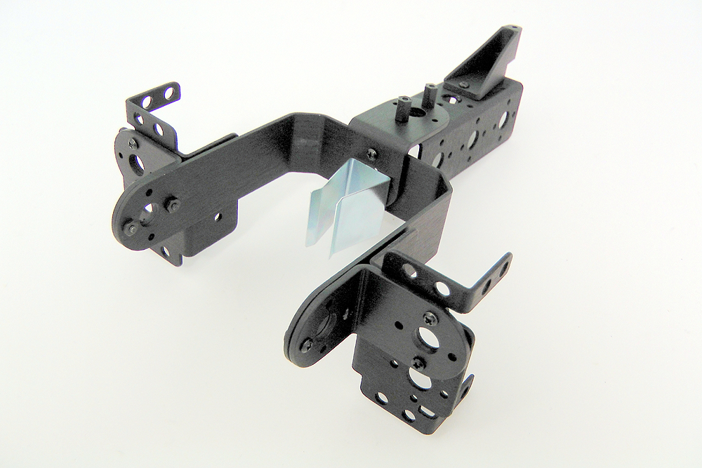 Figure 5. |
||||
| Step
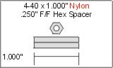
6. In a new sub-assembly, conect the 1" hex spacers to the SES electronics carrier using four
|
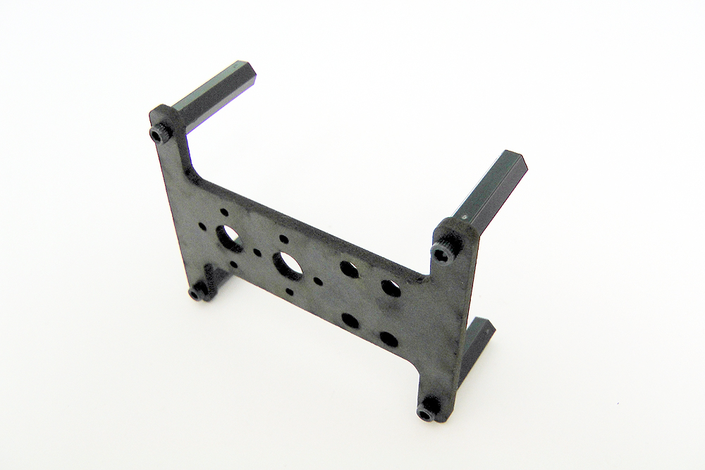 Figure 6. |
||||
| Step
7. Connect the sub-assembly from step 6 to the complete assembly using 2x 2-56 screws as shown in figure 7. The 2-56 screws pass through the SES carrier and are fixed into the small 2-56 hex spacers.
|
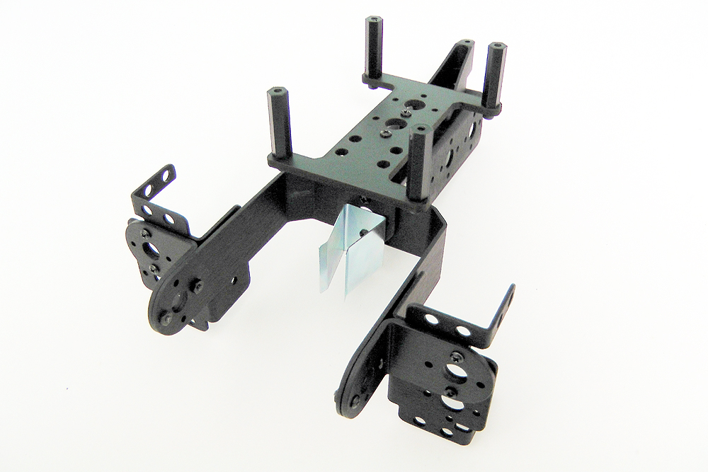 Figure 7. |
||||
| Step 8. Connect a Hitec 1425CR continuous rotation servo motor to each of the multipurpose servo brackets using the servo fastening hardware. The servo should be oriented with the white horn at the bottom. Remove the white servo horn from each servo.
|
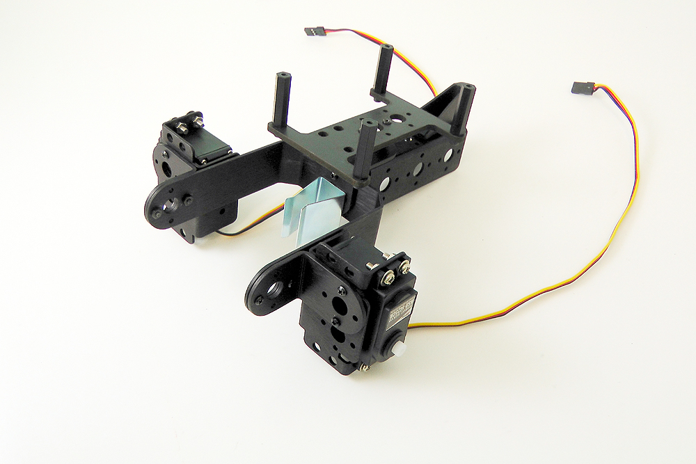 Figure 8. |
||||
| Step
9. Wrap each of the two servo wheels with the black rubber band, ensuring proper spacing around the wheel. Two spare rubber bands are included. Press the servo wheel onto the servo's spline (this is a press fit and needs to be oriented correctly). Use the screws which previously held the white servo horns in place on the servos to now hold the wheels in place. |
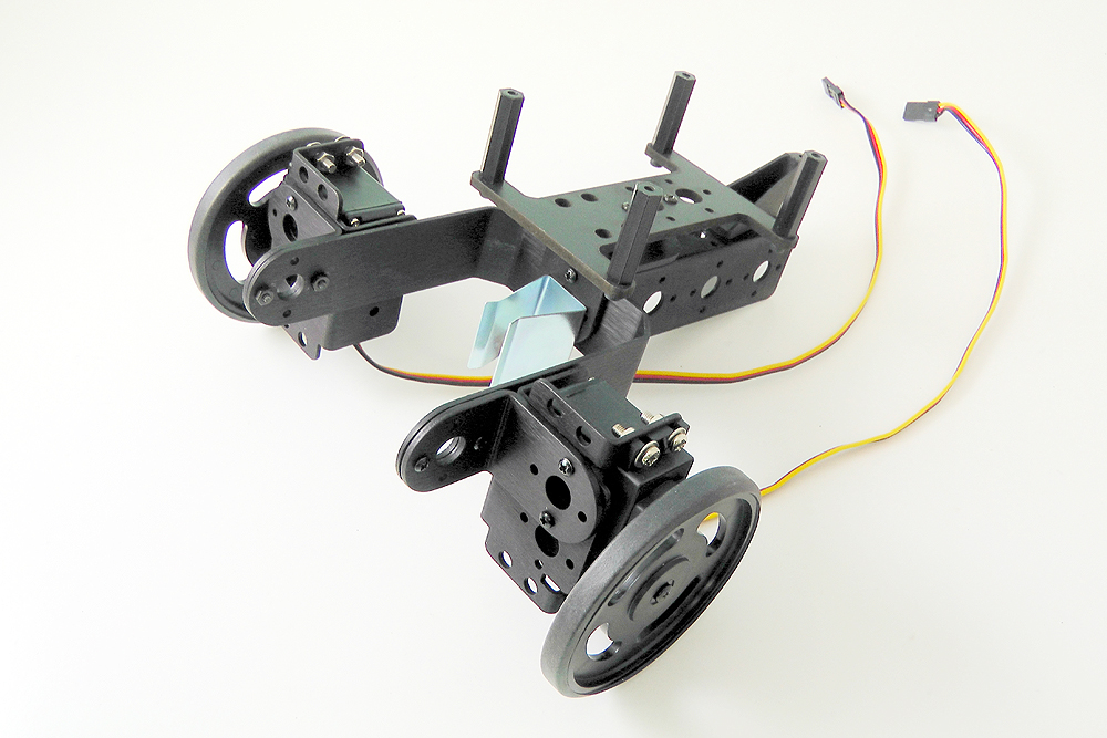 Figure 9. |
||||
| Step
10. Use two pairs of pliers / vice or other means to bend the metal rod used to the tail wheel. The bend should be in the same axis as the horizontal wheel support. This will allow the wheel to pivot more easily than if the wheel were simply vertical. The bend can be around 15-35 degrees; the wheel should not contact the C-channel when it is installed and should be enough to rotate the wheel. |
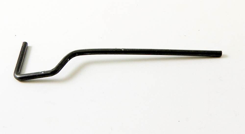 Figure 10. |
||||
| Step
11. Install one lock collar 1" from the top of the rod using the small set screw and hex key provided. Insert the wheel onto the lower part of the rod and secure it in place using another lock collar with set screw. The wheel should spin freely. |
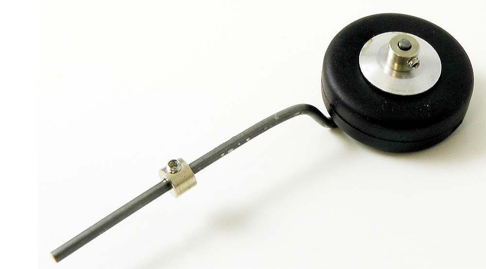 Figure 11. |
||||
| Step
12. Attach this tail wheel sub-assembly to the frame and fasten it in place using the remaining lock collar and set screw. If you want, you can adjust the height of the tail wheel so the robot is horizontal. |
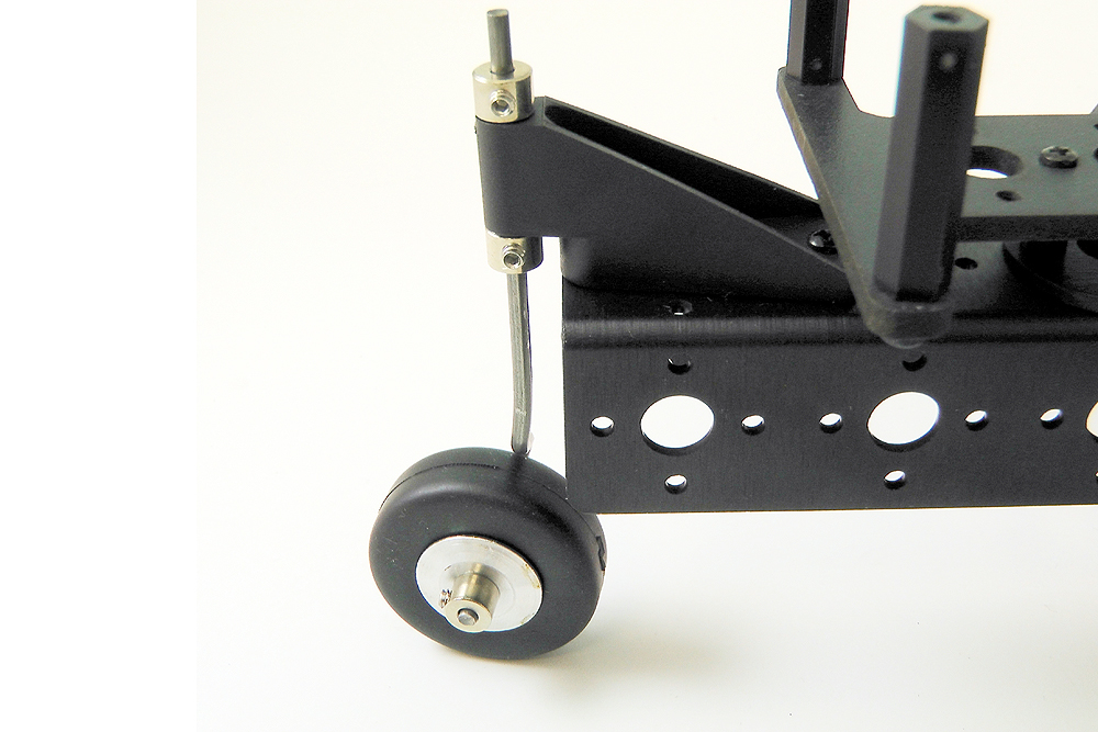 Figure 12. |
||||
| Step
13a (SSC-32 or BotBoarduino). Install the battery connector / wiring harness through one of the holes at the front. Install the 9V battery connector / wiring hardness through the hole on the opposite side. Refer to figure 13a for proper placement. |
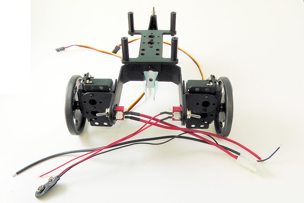 Figure 13a. |
||||
| Step
13b (SSC-32U Only). Install the battery connector / wiring harness through one of the holes at the front. Refer to figure 13 for proper placement. The 9V harness is not needed when only using the SSC-32U |
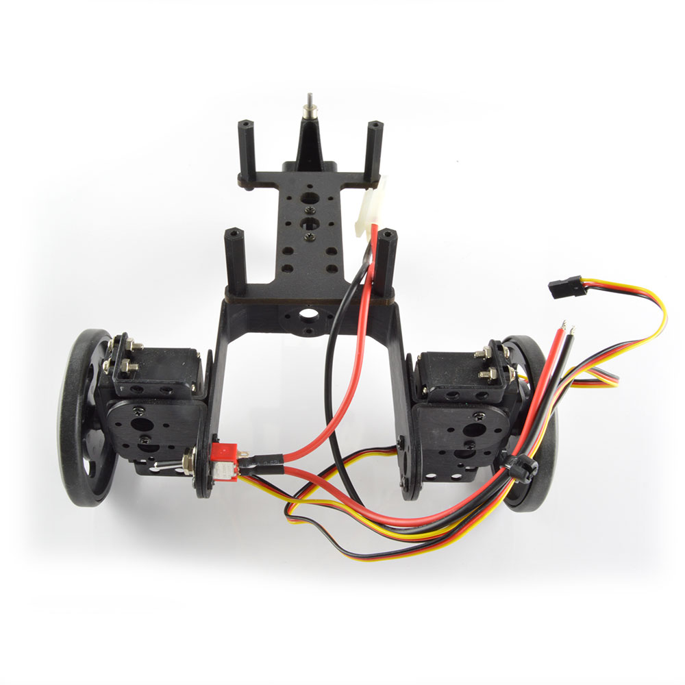 Figure 13b. |
||||
| Step
14a. (SSC-32). Open all four green terminal blocks by loosening each of the screws at the top. Connect the thinner 9V battery wires to the VL terminals with red going to '+' and black going to '-' and turn the screw the other direction so the wire is held in place. Connect the larger battery wires to the VS terminals, ensuring there are no stray wires which may create a short circuit. IMPORTANT: REMOVE the VS=VL jumper |
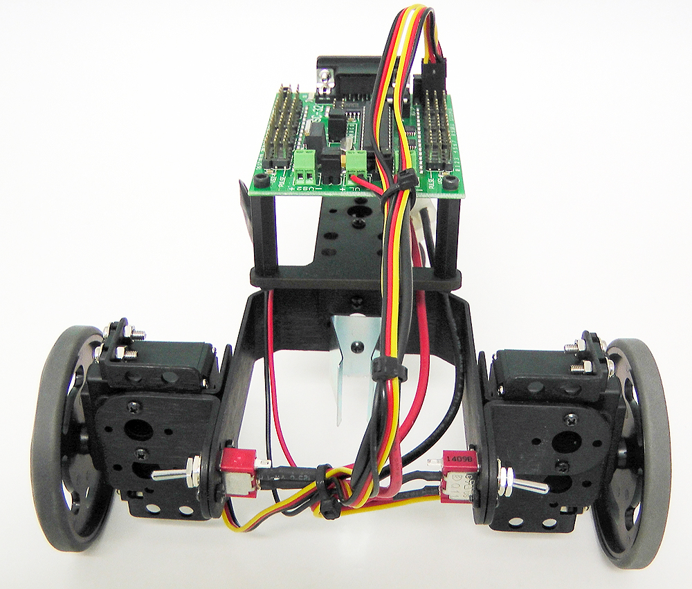 Figure 14a. |
||||
| Step
14b. (BotBoarduino). Open the green VS terminal blocks by loosening each of the screws at the top. Connect the larger battery wires to the VS terminals, ensuring there are no stray wires which may create a short circuit. IMPORTANT: Change the jumper associated with pins #2 to #5 to VS rather than 5V. This jumper is located to the right of the large ATMEGA328 chip on the BotBoarduino (refer to the BotBoarduino Guide for more information). |
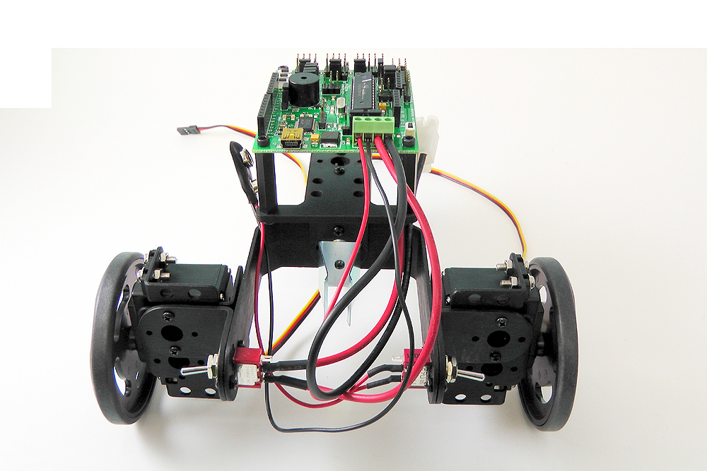 Figure 14b. |
||||
| Step
14c (SSC-32U). Open the green VS1 terminal blocks by loosening each of the screws at the top. Connect the larger battery wires to the VS terminals, ensuring there are no stray wires which may create a short circuit. Leave the VL=VS jumper in place, as well as the VS1=VS2 jumpers. |
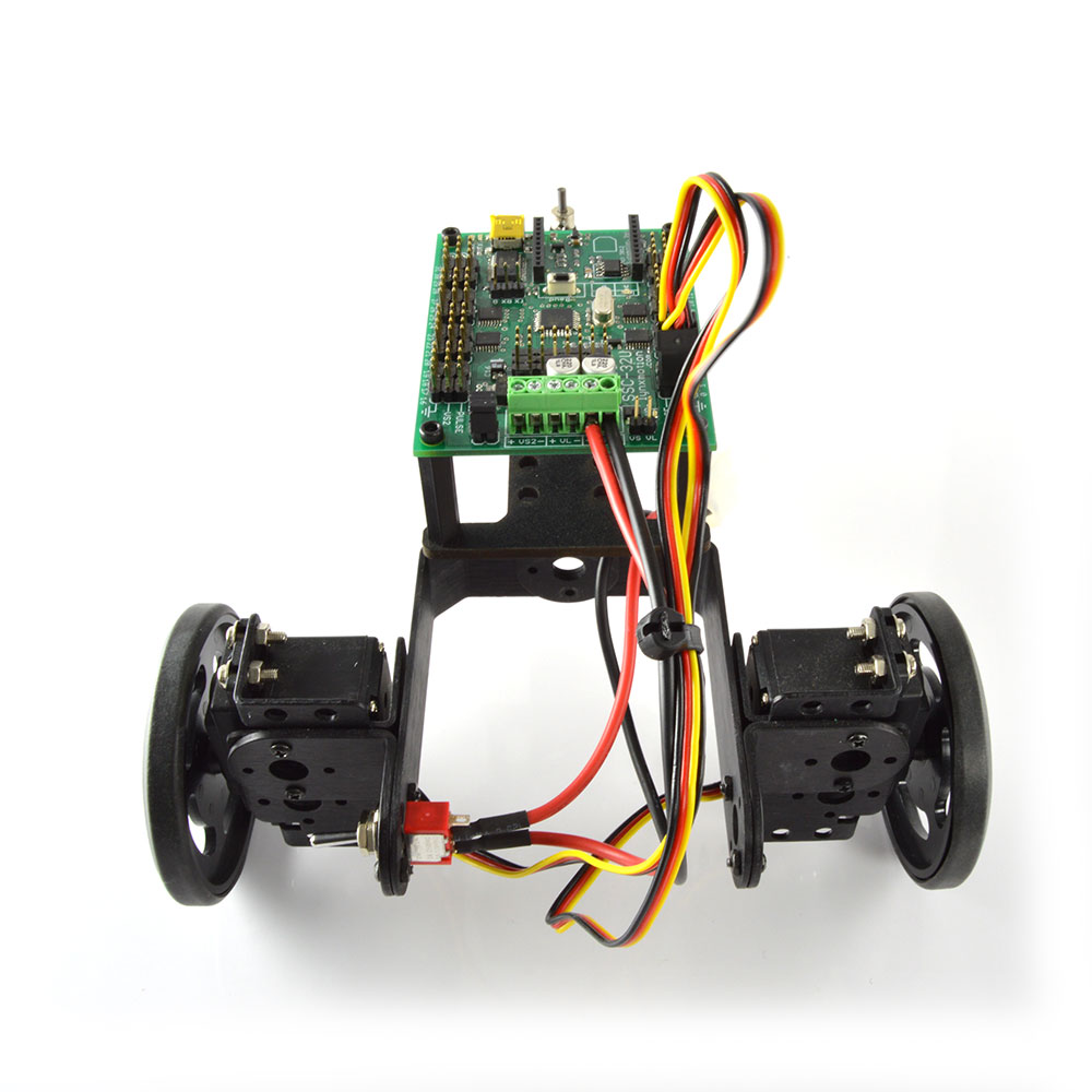 Figure 14c. |
||||
| Step
15a (SSC-32 / SSC-32U) Connect the two servos to pins on the SSC-32, with the black wire being on the outside of the board. Clean up the wires using wire ties, electrical tape or other means. The Lynxmotion 6V, 2800mAh battery is intended to fit snugly between the SES carrier and the BotBoarduino. Connect the servo on the left side for pin 0 and the servo on the right side to pin 1 on the SSC-32.
|
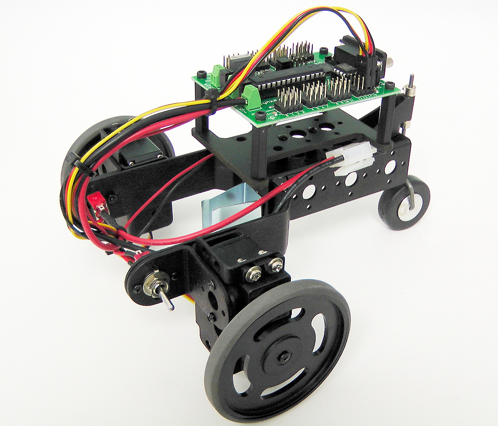 Figure 15a. |
||||
| Step
15b (BotBoarduino) Connect the two servos to pins 3 and 4 on the botboarduino, with the black wire being on the outside pin. Clean up the wires using wire ties, electrical tape or other means. The 6V, 2800mAh battery is intended to fit snugly between the SES carrier and the BotBoarduino.
|
Figure 15b. |
||||
|
Step 16a. (SSC-32). |
|||||
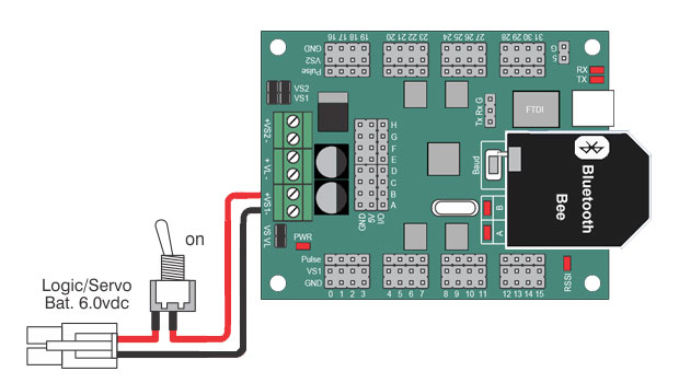
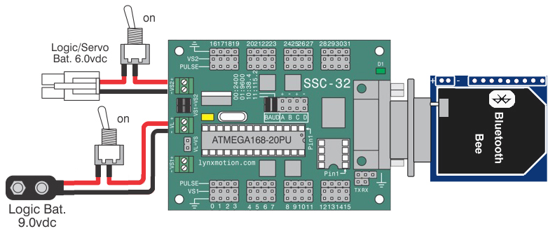 Schematic 16a. SSC-32 (with optional USB to XBee breakout + Bluetooth Bee) |
|||||
| |
|||||
|
Step 16c (SSC-32U). |
|||||
 Schematic 16b. SSC-32U + Bluetooth Bee |
|||||
|
Step 16b. (BotBoarduino). |
|||||
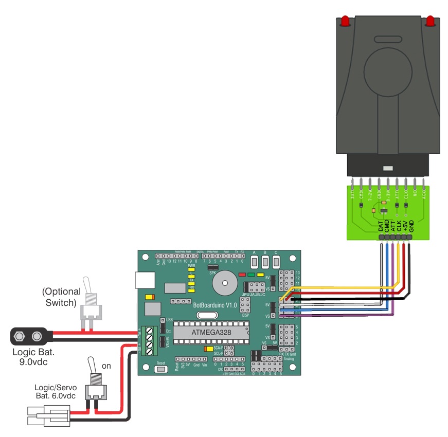 Schematic 16b. BotBoarduino + PS2 |
|||||
| |
|||||
| Step
17. (Optional PS2 for BotBoarduino) IDownload and install the Arduino IDE from www.arduino.cc. In order to control the Rover wirelessly using a PS2 controller, you will need to purchase RC-01 V2 as well as the EC-03 PS2 Receiver Carrier and install them on the robot as shown in figure 17. Once you have done this, connect the PS2 receiver to the BotBoarduino as shown in figure 17. Sample code for controlling the rover using an optional Lynxmotion PS2 remote control can be found on Lynxmotion's Github. The left servo is connected to digital pin 3 and the right servo is connected to digital pin 4. Note: The 9V battery is OPTIONAL; the BotBoarduino's onboard regulator needs a minimum of 5.1V to operate, so if you are using a 6V battery, you can use it to power both VL and VS. However, if you are using a battery below 5V, you will also need a 9V battery to power VL. |
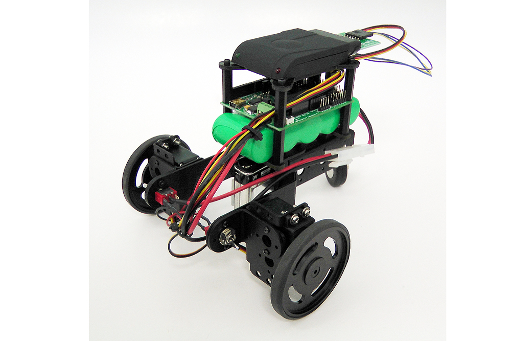 Figure 17. |
||||
| |
|||||
| Step
18a. (SSC-32 / SSC-32U) FlowBotics Studio: The 2WD rover can be controlled wirelessly from Flowbotics Studio (2WD rover project). Download and install FlowBotics Studio and follow the instructions. |
|||||
| |
|||||
| Step
18b. (BotBoarduino) Download and install the Arduino IDE from www.arduino.cc. The left servo is connected to digital pin 3 and the right servo is connected to digital pin 4. In order to control the Rover from the Arduino IDE, you need to send normal servo commands to digital pins 3 and 4. More information about the servo library can be found on the Arduino website. Note: The 9V battery is OPTIONAL; the BotBoarduino's onboard regulator needs a minimum of 5.1V to operate, so if you are using a 6V battery, you can use it to power both VL and VS. However, if you are using a battery below 5V, you will also need a 9V battery to power VL. |
|||||
.GIF)