A4WD1 Tutorial for Autonomous Behavior v1.0
| A4WD1 Tutorial for Autonomous Behavior v1.0
Updated 12/20/2011 Safety first! Wear eye protection and never touch a powered robot! Note: Do not use Loctite or thread locks on the assembly. They are not necessary and may cause damage to the Lexan. Note: This guide follows the assembly guide. The Sabertooth has already been installed. Software: |
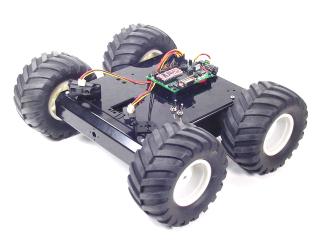 Image of A4WD1. |
||||||||||||||||||||
|
|
|||||||||||||||||||||
| Step 1. Mounting the Bot Board II Add the four standoffs for the Bot Board II to the robot's top panel as shown. Use four .250" hex socket head screws.
|
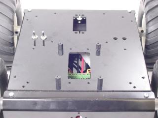 Figure 1. |
||||||||||||||||||||
| Step 2. Install the Bot Board as shown, using four of the .250" 4-40 screws. Install the Atom Pro chip as shown.
|
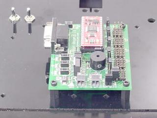 Figure 2. |
||||||||||||||||||||
| Step 3. Connecting Sabertooth to Bot Board II The Sabertooth 2x10 R/C was primarily designed to be connected to a remote control receiver. It has a BEC (battery elimination circuit) that puts 5vdc on the red wires to power the receiver. Because the Bot Board II has its own power supply, it is necessary to bypass the BEC. Use an exacto knife to carefully pry the black tab up and slip the red wire out of the black housing as shown in Figure 3. Bend the red wires up and use electrical tape to cover them as shown. This will prevent accidental shorts. |
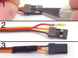 Figure 3. |
||||||||||||||||||||
| Step 4. Refer to Table 4 and the schematic (Figure 4) for Bot Board II and Sabertooth wiring connections. Double check your wiring. Make sure the red battery wire goes to the (+) terminal! |
|
||||||||||||||||||||
| Step 5. Set the Sabertooth switches to the settings listed in Table 5 and Figure 5.
|
 Figure 5. |
||||||||||||||||||||
|
Schematic - Figure 5. |
|||||||||||||||||||||
| Step 6. Programming the Atom Pro Download the BASIC Micro Studio development software. Install and run the program on your PC. The goal here is to load a program into the editor and program the Atom Pro with the code. You can use the serial port (D shaped connector with 9 pins sticking out) or a USB-to-serial cable. If you go the USB-to-serial cable route buy a good quality name brand unit. When you have a feel for the program you can load and program your Basic Atom with the BASIC programs listed below. Now it's time to have some fun! |
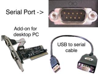 Figure 6. |
||||||||||||||||||||
| Step 7.
Differential or Tank Mode Test (Required) Download this file (a4wd1tst2.zip) and run it. For this program, on the Bot Board II, the "A" button is left channel throttle, "C" button is right channel throttle, and "B" is a speed and direction reset. This program requires the Sabertooth's Switch 1 to be flipped to the "Off" or "Independent Control" position. Upon powering up the robot, you should hear four ascending notes. Pressing A once results in a beep and slow forward motion (10%) on the left channel only. Pressing nine more times results in 100% power. Continuing to press A will make the motor act as above, except only for the right channel. The C button will control the left motor in a similar manner. Pressing the B button will reset the speed and direction of both left and right. Note: The Sabertooth's red Error LED will light to indicate overheating or current limit. The green Status1 LED will glow dimly when power is applied, and brightly when it's receiving pulses from the microcontroller. The green Status2 LED will flash out the detected number of lithium cells when lithium mode is enabled. |
|||||||||||||||||||||
| Step 8.
Throttle and Steering Mode Test (Optional) This program requires the Sabertooth's Switch 1 is flipped into the "On" or "Enable Mixed Mode" position! Download this file (a4wd1tst1.zip) and run it. For this program, on the Bot Board II, the "B" button is throttle and the "A" and "C" buttons are steering. Upon powering up the robot, you should hear four ascending notes. Pressing B once results in a beep and slow forward motion (10%). Pressing nine more times results in 100% power. After the motor is at 100% power, pressing B will reduce the speed in 10% increments until it stops. Continue to press B to make the robot move as above, only in reverse. Press Reset, then B twice. Now press C a few times to see the robot make a gradual left turn. Pressing A a few times will return to forward motion, and continuing to press A will result in gradual right turn. Experiment with these buttons to understand how throttle and steering can be used to control the vehicle's motion. Note: The Sabertooth's red Error LED will light to indicate overheating or current limit. The green Status1 LED will glow dimly when power is applied, and brightly when it's receiving pulses from the microcontroller. The green Status2 LED will flash out the detected number of lithium cells when lithium mode is enabled. When you're done with this testing program, flip the Sabertooth's Switch 1 back into the "Independent
Control" position! |
|||||||||||||||||||||
| Step 9. Now it's time to set up the A4WD1 for autonomous behavior. The code supports three Sharp GP2D12 sensors; two in the front and one in the back. |
|
||||||||||||||||||||
| Step 10. Attach two GP2D12 sensors to the chassis as shown, using either double-sided foam tape or optional multi-purpose sensor housing brackets. The exact angle isn't critical, but will affect the robot's behavior. Experimentation is encouraged. Make sure you place the robot's right sensor on the robot's right side, facing left! Place the robot's left sensor on the robot's left side, facing right! This overlap ensures there isn't a blind spot in the center. If you switch the positions of the sensors accidentally, the robot will turn into objects, instead of away. Attach the other GP2D12 sensor at the rear of the robot as shown. Use double-sided foam tape to hold it in place. |
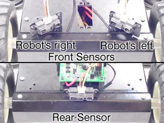 Figure 10. |
||||||||||||||||||||
|
Schematic - Figure 11. |
|||||||||||||||||||||
| Step 12. Download this file (4wd1auto.zip) and program the Atom Pro. You will want to set the bot on something so that the wheels aren't touching the ground. This program allows the robot to roam around the room without bumping into things. It uses three Sharp GP2D12 analog distance sensors to "see" things in its environment. Feel free to experiment with the variables and math in the main section of the program. The robot does a very good job navigating without getting stuck. The motor control is based on the GP2D12 sensors with a bias for forward motion. The robot will sometimes back up and turn even though there are no specific instructions to do so. Look for this and other emergent behaviors during your experimentation. |
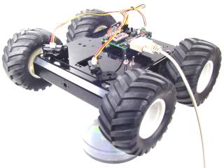 Figure 12. |
||||||||||||||||||||