A4WD1 Gripper Assembly Instructions v1.0
Last modified by Eric Nantel on 2023/01/27 14:32
| A4WD1 Gripper Assembly Instructions Rev. 1.
Updated 10/09/2007. Safety first! Wear eye protection and never touch a powered robot! Note: Do not use Loctite or thread locks on the chassis assembly. They are not necessary and may cause damage to the Lexan. |
 4WD1 Gripper |
||||||||
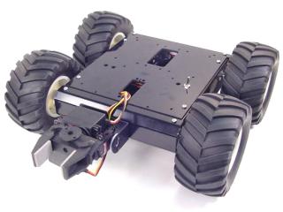
| Step 1. Open up the top of the rover to get access to the inside. Install the "C" bracket onto the front A4WD1 bracket. Use two of the 1/4" x 2-56 screws and two 2-56 nuts.
|
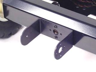 Figure 1. |
||||||||
| Step 2. Use two 1/4" x 2-56 screws and two 2-56 nuts to attach the the two multi-purpose brackets together as shown in Figure 2.
|
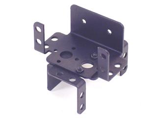 Figure 2. |
||||||||
| Step 3. Follow the diagram below to attach the multi-purpose brackets to the "C" bracket. |
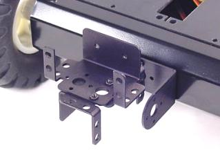 Figure 3-2. |
||||||||
 Figure 3-1. |
|||||||||
| Step 4. Attach the servo using four snap rivet fasteners and two #2 tapping screws.
|
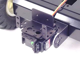 Figure 4. |
||||||||
| Step 5. Remove the servo horn from the second servo and attach it using four rivet fasteners. Set the servo screw aside.
|
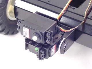 Figure 5. |
||||||||
| Step 6. Install the gripper, fastening it using the servo screw you removed in Step 5. Tighten this down snugly. |
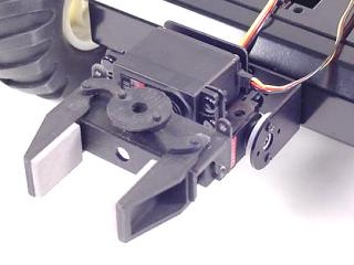 Figure 6. |
||||||||
| Step 7. Make sure the servo is aligned to mid-position, and the gripper is halfway open. Now the servo and gripper will be aligned correctly. Remove the servo screw and horn. Slide the servo into the gripper from the bottom. You may need to wiggle it a bit to get it seated properly. Use the servo screw to attach the servo. Tighten this down, but then unscrew it half a turn. Too much friction can bind the servo. |
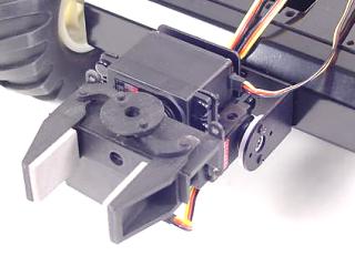 Figure 7. |
||||||||
| Step 8. This completes the mechanical assembly of the gripper. |
Figure 8. |
||||||||