A4WD1 & Tri-Track Hitec RC Control Tutorial v2.0
| A4WD1 R/C Stick Radio Control Tutorial Rev. 2.
Updated 06/24/2009. Safety first! Wear eye protection and never touch a powered robot! Note: Do not use Loctite or thread locks on the assembly. They are not necessary and may cause damage to the Lexan. Note: This guide follows the assembly guide. The Sabertooth has already been installed. |
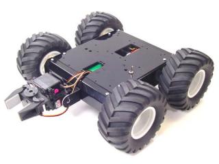 A4WD1 Rover. |
||||||||||||||||||||||||
| Step 1. If you do not plan on adding servos to the robot you can just plug the Sabertooth into the receiver as shown in figure Figure 1. Make sure the yellow wires are toward the middle of the receiver. Then you can move on to Step 5.
|
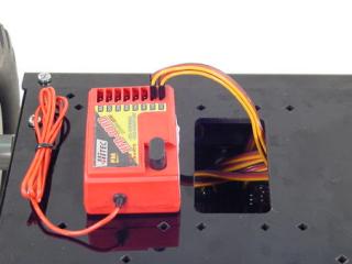 Figure 1. |
||||||||||||||||||||||||
| Step 2. The Sabertooth 2X10 RC has a feature called battery elimination circuit (BEC) that provides power to the RC receiver. It can provide enough current to power the receiver alone, but not if servos are used. In order to provide enough power for the receiver and the servos attached to it, we need to add a separate battery pack. In addition, we need to bypass the Sabertooth's BEC to prevent it from interfering with the separate battery pack. Use an exacto knife to carefully pry the black tab up and slip the red wire out of the black housing as shown in Figure 2. Bend the red wires up and use electrical tape to cover them as shown. This will prevent accidental shorts. |
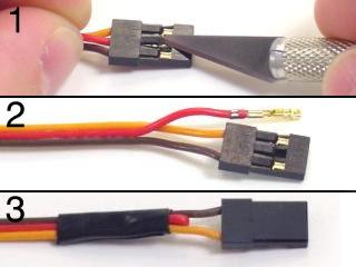 Figure 2. |
||||||||||||||||||||||||
| Step 3. Plug the Sabertooth into the receiver as shown. Make sure the yellow wires are toward the middle of the receiver.
|
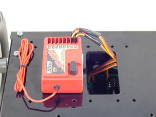 Figure 3. |
||||||||||||||||||||||||
| Step 4. Plug the battery's wiring harness from the radio into the receiver as shown. Make sure the black wire is on the outside of the receiver. You can also use our BATC-01 in order to use our rechargeable 6.0vdc batteries for this step. This is shown in the schematic Figure 4-2.
|
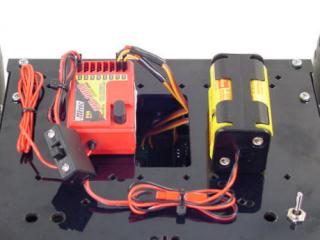 Figure 4. |
||||||||||||||||||||||||
|
Schematic - Figure 4-2. |
|||||||||||||||||||||||||
| Step 5. Make sure your Sabertooth's dip switches are in the default positions, as shown in Figure 5. It would be a good idea to read the Sabertooth manual to familiarize yourself with the different settings. With the default settings, you can now control the rover. |
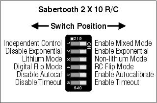 Figure 5. |
||||||||||||||||||||||||
| Step 6. Remove the battery case from the bottom of the radio to show the servo option switches. Set them as listed in Table 6. |
|
||||||||||||||||||||||||
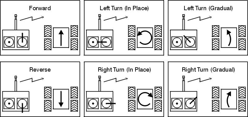
| Step 7. The complete robot controls are listed in Table 7.
|
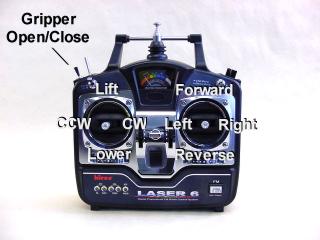 Figure 7. |
||||||||||||||||||||||||
| Step 8. Refer to Figure 8 for information on controlling the robot.
|
|||||||||||||||||||||||||