A4WD1 & Tri-Track Spektrum RC Control Tutorial
| A4WD1/Tri-Track Spektrum R/C Stick Radio Control Tutorial
Updated 04/20/2011 Safety first! Wear eye protection and never touch a powered robot! Note: Do not use Loctite or thread locks on the assembly. They are not necessary and may cause damage to the Lexan. |
 Tri-Track and A4WD1 Rover with DX5 |
||||||||||||||||||||
Step 1. Use an exacto knife to carefully pry the black tab up and slip the red wire out of the black housing as shown in Figure 1. Bend the red wires up and use electrical tape to cover them as shown. This will prevent accidental shorts. |
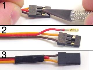 Figure 1. |
||||||||||||||||||||
Step 2.
|
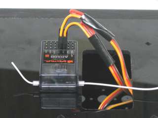 Figure 2. |
||||||||||||||||||||
Step 3. |
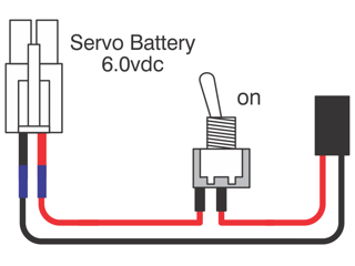 Figure 3. |
||||||||||||||||||||
|
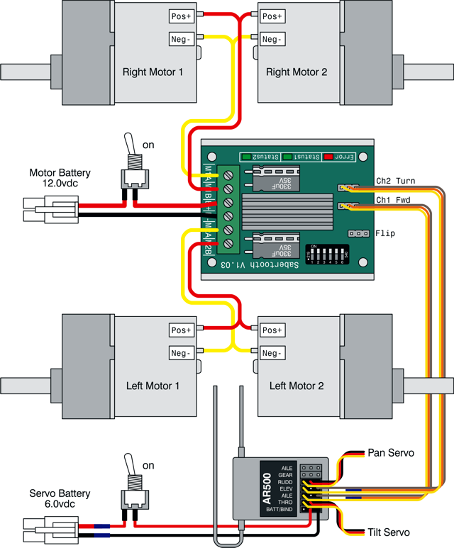
Schematic. |
|||||||||||||||||||||
| Step 4. Bind the transmitter to the receiver. Refer to the Spektrum manual for detailed instructions. |
 Figure 4. |
||||||||||||||||||||
| Step 5. Make sure your Sabertooth's dip switches are in the default positions, as shown in Figure 5. It would be a good idea to read the Sabertooth manual to familiarize yourself with the different settings. With the default settings, you can now control the rover although the controls will be reversed. This will be corrected later. |
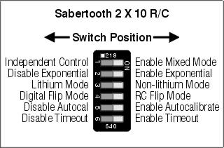 Figure 5. |
||||||||||||||||||||
| Step 6. (Optional Pan and Tilt) If you are not installing a Pan and Tilt you can skip down to step 8, ignoring this step. Punch the cutout out of the top panel. |
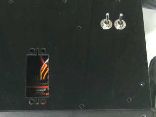 Figure 6. |
||||||||||||||||||||
Step 7. (Optional Pan and Tilt)
|
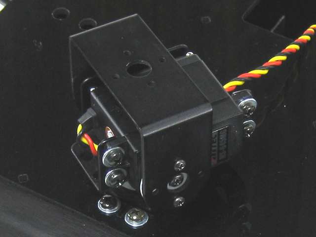 Figure 7. |
||||||||||||||||||||
| Step 8. To set the controls to behave normally, you must adjust the servo option switches. They are located on the front of the remote. Set them as listed in Table 8. |
|
||||||||||||||||||||
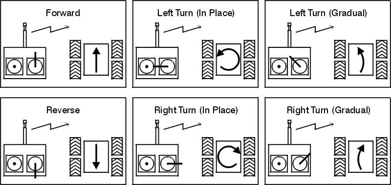
| Step 9. Refer to Figure 9 for information on controlling the robot.
|
|||||||||||||||||||||