A4WD1 Chassis Assembly Guide
| A4WD1 Chassis Assembly Guide.
Updated 12/20/2011 Safety first! Wear eye protection and never touch a powered robot! Note: Loctite or thread locks can be used on the construction of the aluminum components. However, don't use them with Lexan, as they are not necessary and may cause damage. Note: These instructions cover several different configurations of the A4WD1 robot kits. Not every step will pertain to your kit. |
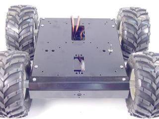
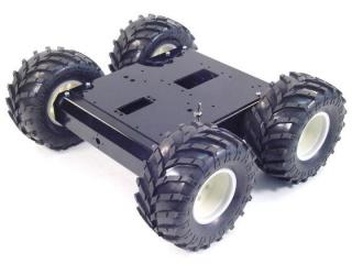 Image of completed 4WD. |
||||||||||||||||
| Lexan Preparation. The lexan pieces have a protective covering that needs to be removed before assembly. When the laser cuts, the covering melts into the cut edge which can make removal difficult. If you gently scrape the cut edge with a flat blade screwdriver, the covering can easily be lifted and peeled off. On smaller pieces the coverings can be more difficult to remove. If you have trouble you can gently scrape the cut edge, then use duct tape to lift the covering off. For further information on lexan, see this page. |
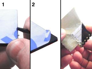 Lexan Preparation. |
||||||||||||||||
| Step 1. Push the motor wire connectors on the terminals as shown. Make sure you put the red to (+) and the yellow to (-). This will make wiring the speed controllers easier later on. However, if you would like to solder the wires instead, feel free. It does make for a better connection. |
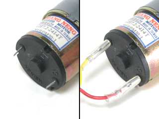 Figure 1. |
||||||||||||||||
| Step 2. Mount the motors into the chassis side brackets as shown, using eight of the 3mm x 6mm screws.
|
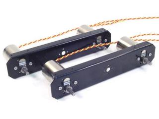 Figure 2. |
||||||||||||||||
| Step 3. If you are using the PGHM-01 motors, use three 3mm x 6mm screws and refer to Figure 4 for mounting instructions.
|
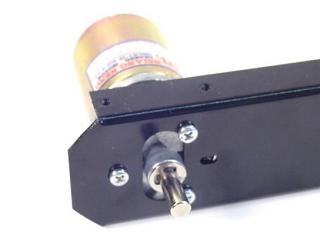 Figure 3. |
||||||||||||||||
| Step 4. Use eight of the 3mm x 6mm screws to connect the chassis end brackets as shown.
|
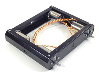 Figure 4. |
||||||||||||||||
| Step 5. Use four of the 3mm x 6mm screws to attach the bottom lexan panel.
|
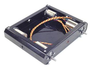 Figure 5. |
||||||||||||||||
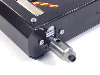
| Step 6. Thread the tire-connection screw into the hub as shown, then put the hub on the motor shaft. Tighten the set screw down tightly. |
|
||||||||||||||||
| Step 7. Remove the tire-connection screws, and attach the tires. Make sure to align the tire treads properly. |
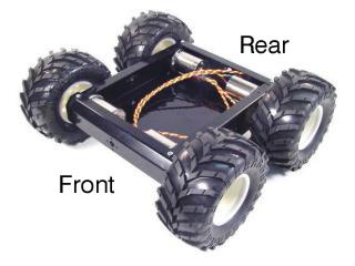 Figure 7. |
||||||||||||||||
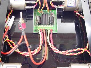
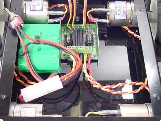
| Step 8. Use double sided foam tape to attach the motor controller inside the chassis. Refer to Table 9 for connection information.
|
|
||||||||||||||||
|
Schematic - Figure 8-2. |
|||||||||||||||||
| Step 9. For a single 12vdc battery, use double sided foam tape or velcro to attach the battery pack inside the chassis. Plug the battery into the wiring harness. Make sure the power switch is in the "Off" position! |
|
||||||||||||||||
| Step 10. For longer run time, two higher capacity 6.0vdc batteries can be used. Just solder the wiring harness to the battery quick connect cable (BATC-01) as shown. |
|||||||||||||||||
|
Schematic - Figure 10. |
|||||||||||||||||
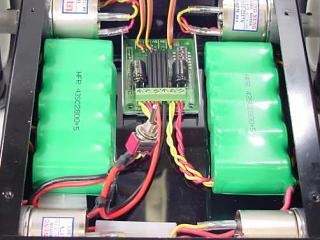
| Step 11. Use double sided foam tape or velcro to attach the battery packs inside the chassis as shown. Plug the batteries into the wiring harness plugs. Make sure the power switch is in the "Off" position! |
|
||||||||||||||||
| Step 12. Attach the power switch in one of the switch holes in the top lexan panel. Use four screws to attach the top panel. This completes the mechanical assembly of the robot. Move on to one of our tutorials for further development. A note for outdoor use: The aluminum components are coated black. If you are operating the robot in rough outdoor terrain (sharp rocks, etc.) you might want to protect the bumpers from scratches. You can spray paint these parts with several thin coats of flat black acrylic to add some scratch protection. You can also place a piece of black electrical tape along the bottom and first section to further protect them. |
|
||||||||||||||||