| Dual
H Bridge Motor Driver. 01.22.04
This is a step-by-step procedure of
connecting a Lynxmotion Dual H-Bridge motor driver to the OOPic-R
microcontroller. These two products were designed at about the same
time, but a misunderstanding of the actual pinout for the connector
resulted in a mismatch. However it's not a difficult fix. Follow the
instructions below to get your project up and running quickly.
|
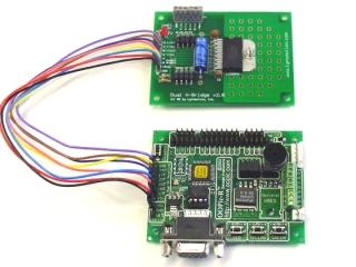
Finished Project |
| |
| Step 1. Plug
in the +5vdc / GND connector (red and black wires) as shown. If
you are already using the serial LCD port, then any I/O bus connector
with +5vdc available can be used. Take care not to install this
backwards. |
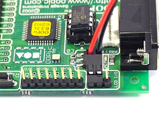
Figure 1-1. |
| |
Step
2. You need to rearrange some of the wires, and to do so you must unplug
them from the black housings. Use a hobby knife and gently slide
it under the tab holding the wire in. Lift the tab and slide the wire
out. Don't bend it too far as damage could result. You will need to remove the following wires:
| 4-wire
housing |
| Wire
Color |
From
DHB |
| Brown |
(A (-) in) |
|
Dark Blue |
(B (+) in) |
|
Pink |
(B (-) in) |
| 2-wire
housing |
| Wire
Color |
From
DHB |
|
Yellow |
(A enable) |
| Light
Blue * |
(B
enable) |
| Table
2-1 |
* The Light Blue (B
enable) wire can optionally be removed and repositioned so that the 2-wire connector will be facing the same way
as the 4-wire connector. It's purely an aesthetic choice.
|
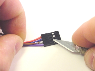
Figure 2-1. |
| |
Step
3. Now you need to insert the wires into the black housings in a
different order. Look at the "Dual DC Motor I/O" section on
the OOPic-R board, and match the numbers by the pins to the correct
wire from the Dual H-Bridge board. Then simply slide the wires back into
the correct slot of the housing. If you make a mistake, just follow
Step 2 to get the wire out again.
|
4-wire housing |
|
OOPic-R
Pin Number
|
Wire Color |
From
DHB
|
| 24 |
Purple |
(A
(+) in) |
| 17 |
Yellow |
(A
enable) |
| 25 |
Brown |
(A
(-) in) |
| 26 |
Dark
Blue |
(B
(+) in) |
|
2-wire housing |
|
OOPic-R
Pin Number
|
Wire
Color
|
From
DHB
|
| 18 |
Light
Blue |
(B
enable) |
| 27 |
Pink |
(B
(-) in) |
| |
Table 3-1 |
|
|
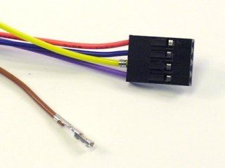
Figure 3-1.
|
| |
| Step
4. Your wires should look like the picture when you are done. If they
are in the wrong order, then refer to Table 3-1 for the wire order. |
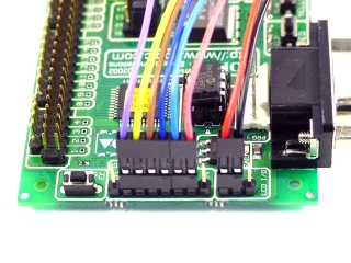
Figure 4-1. |
| |
| Step 5. On
the Dual H-Bridge, attach wires from the battery and the motors as the
diagram shows. Take care to observe polarity to prevent
problems. |
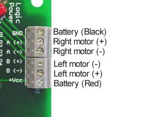
Figure 5-1. |
| |
|
Step 6. This code will
give you a good start on making your bot move around and be able to
change direction with only two variables. By Jim
Babcock. |
| |
' This
small program is designed to give you the basics to move your bot around
' and change direction with just 2 variables (speed and turn)
' Speed is a value between 127 and -128 with 0 being neutral Or
Stop
' When speed is set from 1 to 127 the bot will move forward and
faster As the value goes up
' When speed is set from -1 to -128 the bot will move backward
and faster As the value goes down
' Turn is a value between 127 and -128 with 0 being no turn at all
' When turn is set from 1 to 127 the bot will move to the left. As the value goes up the bot turns harder.
' When turn is set from -1 to -127 the bot will move to the right. As the value goes down the bot turns harder.
' It should be noted that since the objects Navcom, LeftMotor,
and RightMotor have been linked
' by Virtual Circuit that the main() program doesn't have to be
loop for the bot to keep moving since the VC is
' constantly running in the background. By the way VCs run about 5
times faster the the other code.
Dim RightMotor As New oDCMotor2 ' Right motor bank
Dim LeftMotor As New oDCMotor2 ' Left motor bank
Dim Turn As New oWord ' One number used to turn both left
and right using the object Navcon through VC
Dim Speed As New oWord ' One number used to
command both forward and reverse using the object Navcon through VC
Dim Nav As New oNavCon ' Object used to command your bot around using one speed value
and one turn value
Sub main()
Call motorsetup ' Sub program to set your
motors up to run. (Only used once)
Speed.signed = 1 ' Sets up the value property
to use positive and negative numbers 127 to -128
turn.signed = 1 ' Sets up the value property
to use positive and negative numbers 127 to -128
Speed = 2 ' Change this variable to
control speed and direction in this small program
Turn = 0 ' Change this variable to
control left Or right turning in this small program
Nav.Input1.Link(Speed) ' Links the speed variable to the Navcon object
Nav.Input2.Link(Turn) ' Links the turn variable to the Navcon object
Nav.Output1.Link(LeftMotor) ' Links the first output of Navcon
to LeftMotor value using VC
Nav.Output2.LInk(RightMotor) ' Links the second output of Navcon
to RightMotor value using VC
Nav.Limit = cvTrue ' Limits the left and right motor values from 127
to -128
Nav.Operate = 1 ' Used to make this object active in the list
loop
End Sub
'**************************************************************************
'
'**************************************************************************
Sub motorsetup ()
LeftMotor.IOLineP = 17 'Enable line of motor control PWM is used IOLINE P
leftMotor.InvertoutD=cvTrue 'Changes direction moves when
commanded forward
leftMotor.prescale=2 'Used to step down the
frequ. of PWM
leftMotor.period=255 'Used to set resalution of PWM (# of steps
for value)
LeftMotor.IOLine1 = 24 'First control line for an L293 H-Bridge IOLINE 1
LeftMotor.IOLine2 = 25 'Second control line for an L293 H-Bridge IOLINE 2
LeftMotor.Operate = 1 'Used to make this object active in the list looop
LeftMotor.Brake = cvOff 'Makes sure brake is set to
off
LeftMotor.value = cvOff 'Makes sure motor value set
to 0
RightMotor.IOLineP = 18 'Enable line of motor control PWM is used IOLINE P
RightMotor.InvertoutD=cvTrue 'Changes direction moves when
commanded forward
RightMotor.prescale=2 'Used to step down the
frequ. of PWM
RightMotor.period=255 'Used to set resalution of PWM (# of steps
for value)
RightMotor.IOLine1 = 26 'First control line for an L293 H-Bridge IOLINE 1
RightMotor.IOLine2 = 27 'Second control line for an L293 H-Bridge IOLINE 2
RightMotor.Operate = 1 'Used to make this object active
RightMotor.Brake = cvOff 'Makes sure brake is set to
off
RightMotor.value = cvOff 'Makes sure motor value set
to 0
End Sub |
|
