Tri-Track Tutorial for PS2 Control v1.0
| Tri-Track Tutorial for PS2 Control v1.0
Updated 07/19/2010 Safety first! Wear eye protection and never touch a powered robot! Note: Do not use Loctite or thread locks on the assembly. They are not necessary and may cause damage to the Lexan. Note: This guide follows the assembly guide. The Sabertooth 2x5 R/C has already been installed. Software: |
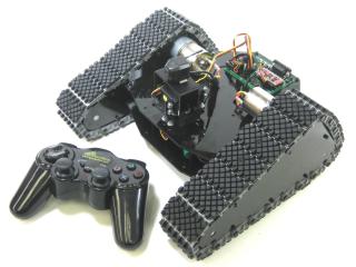 Image of Tri-Track Chassis. |
||||||||||||||||||||||||||||||||||||||||||||||||||||||
| Step 1. Mounting the Bot Board II Install the Atom Pro chip into the Bot Board II as shown. Add the four 1.0" standoffs to the Bot Board II, then install as shown using four of the .250" 4-40 screws.
|
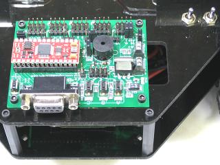 Figure 1. |
||||||||||||||||||||||||||||||||||||||||||||||||||||||
| Step 2A. Connecting Sabertooth to Bot Board II The Sabertooth 2x5 R/C was primarily designed to be connected to a remote control receiver. It has a BEC (battery elimination circuit) that puts 5vdc on the red wires to power the receiver. Because the Bot Board II has its own power supply, it is necessary to bypass the BEC. To do so, you can remove the VS=5V jumper associated with pins 0 to 3 and connect channel 1 from teh Sabertooth to pin 1 on the Bot Board, and channel 2 on the Sabertooth to channel 1 on the Bot Board. The diagram in step 4 shows Step 2B (different than this new approach). |
|||||||||||||||||||||||||||||||||||||||||||||||||||||||
| Step 2B. Connecting Sabertooth to Bot Board II A different approach than what is explained in Step 2A is to factor in that the Sabertooth 2x5 R/C was primarily designed to be connected to a remote control receiver. It has a BEC (battery elimination circuit) that puts 5vdc on the red wires to power the receiver. Because the Bot Board II has its own power supply, it is necessary to bypass the BEC. Use an exacto knife to carefully pry the black tab up and slip the red wire out of the black housing as shown in Figure 2. Bend the red wires up and use electrical tape to cover them as shown. This will prevent accidental shorts. |
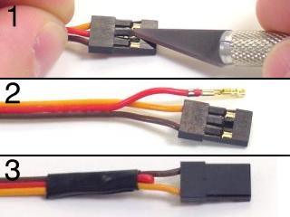 Figure 2. |
||||||||||||||||||||||||||||||||||||||||||||||||||||||
| Step 3. Refer to Table 3 and the schematic (Figure 4) for Bot Board II and Sabertooth wiring connections. Double check your wiring. Make sure the red battery wire goes to the (+) terminal! |
|
||||||||||||||||||||||||||||||||||||||||||||||||||||||
| Step 4. Set the Sabertooth switches to the settings listed in Table 4 and Figure 4.
|
 Figure 4. |
||||||||||||||||||||||||||||||||||||||||||||||||||||||
|
Schematic - Figure 4 (Old approach using Step 2B). |
|||||||||||||||||||||||||||||||||||||||||||||||||||||||
| Step 5. Programming the Atom Pro Download the BASIC Atom Pro IDE development software. Install and run the program on your PC. The goal here is to load a program into the editor and program the Atom Pro with the code. You can use the serial port (D shaped connector with 9 pins sticking out) or a USB-to-serial cable. If you go the USB-to-serial cable route buy a good quality name brand unit. When you have a feel for the program you can load and program your Basic Atom Pro with the BASIC programs listed below. Now it's time to have some fun! |
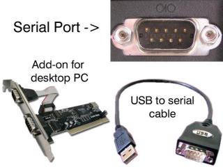 Figure 5. |
||||||||||||||||||||||||||||||||||||||||||||||||||||||
| Step 6.
Differential or Tank Mode Test (Optional) Download this file (a4wd1tst2.zip) and run it. For this program, on the Bot Board II, the "A" button is left channel throttle, "C" button is right channel throttle, and "B" is a speed and direction reset. This program requires the Sabertooth's Switch 1 to be flipped to the "Off" or "Independent Control" position. Upon powering up the robot, you should hear four ascending notes. Pressing A once results in a beep and slow forward motion (10%) on the left channel only. Pressing nine more times results in 100% power. Continuing to press A will make the motor act as above, except only for the right channel. The C button will control the left motor in a similar manner. Pressing the B button will reset the speed and direction of both left and right. Note: The Sabertooth's red Error LED will light to indicate overheating or current limit. The blue Status LED will glow dimly when power is applied, and brightly when a radio signal is present. In Lithium mode, the blue Status LED will flash out the number of lithium cells detected. |
|||||||||||||||||||||||||||||||||||||||||||||||||||||||
| Step 7.
Throttle and Steering Mode Test (Required) Make sure the Sabertooth's Switch 1 is flipped back into the "On" or "Enable Mixed Mode" position! Download this file (a4wd1tst1.zip) and run it. For this program, on the Bot Board II, the "B" button is throttle and the "A" and "C" buttons are steering. Upon powering up the robot, you should hear four ascending notes. Pressing B once results in a beep and slow forward motion (10%). Pressing nine more times results in 100% power. After the motor is at 100% power, pressing B will reduce the speed in 10% increments until it stops. Continue to press B to make the robot move as above, only in reverse. Press Reset, then B twice. Now press C a few times to see the robot make a gradual left turn. Pressing A a few times will return to forward motion, and continuing to press A will result in gradual right turn. Experiment with these buttons to understand how throttle and steering can be used to control the vehicle's motion. Note: The Sabertooth's red Error LED will light to indicate overheating or current limit. The blue Status LED will glow dimly when power is applied, and brightly when a radio signal is present. In Lithium mode, the blue Status LED will flash out the number of lithium cells detected. |
|||||||||||||||||||||||||||||||||||||||||||||||||||||||
| Step 8. Now it's time to set up the robot for PS2 R/C control. The code supports a pan and tilt and gripper, but they are optional. The Pan and Tilt is installed on the front of the top panel, and the gripper is installed on the front of the base. If you are adding a pan and tilt and gripper, you will need to change the power bus jumpers according to Table 8 and Schematic 9.
|
|
||||||||||||||||||||||||||||||||||||||||||||||||||||||
| Step 9. Note, the program allows turning two I/O pins (TTL level peripherals) on or off from the controller. This allows you to add headlights, etc. As a test, you can connect I/O pin 10 or 11 to the "A" and "B" LED / push button enable lines. Connect to the header pins closest to the LED's. You can also use a VOM to measure the voltage on the pins to verify their operation. See the schematic for details. |
|
||||||||||||||||||||||||||||||||||||||||||||||||||||||
|
Schematic - Figure 9. |
|||||||||||||||||||||||||||||||||||||||||||||||||||||||
| Step 10. Download this file (ps2a4wd1.zip) and program the Atom Pro. You will want to set the bot on something so that the wheels aren't touching the ground. Before running the program turn on the PS2 controller. When the program is run it will turn most PS2 game controllers to analog mode (required) automatically. If your controller does not automatically go into analog mode, you will need to do so manually. |
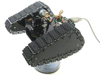 Figure 10. |
||||||||||||||||||||||||||||||||||||||||||||||||||||||
| Step 11. This program lets you control the movement of the bot and several add-on components. Use the left joystick to move the bot forward and backward, and make left and right turns. The turns can be gradual or on-the-spot, depending on how far you push the joystick. This program also incorporates speed limits. There are four speeds, #1 being slowest and #4 being fastest. #3 is default. The speed limit is increased by pressing L1 and decreased by pressing L2. By reducing the top-end speed, you can use the full range of the joystick at a lower speed, thus increasing the accuracy of the rover's movements. This is helpful when trying to position the gripper over an object to pick up. When the program is started, the program will read the joystick positions and set those values as the "nulled" position. Pressing the Start button will null the joysticks on command. Robot movements are proportional to the joystick travel from null, and linear in both directions after the deadband. This helps with PS2 controllers that don't reliably return to 127 for joystick center. See Table 11-1 for a complete list of programmed controls. |
|
||||||||||||||||||||||||||||||||||||||||||||||||||||||