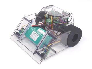
Viper Sumo Assembly Instructions
Last modified by Eric Nantel on 2023/01/30 14:31
| Viper
Online Assembly Instructions.
Chassis Safety first! Wear eye protection and never touch a powered robot! |
 Viper |
| Step 1.
Install the aluminum bars to the underside of the left side panel as shown
Use 7 of the 4-40 x 3/8" screws for each side as shown. The screws
should go in through the Lexan first, then the metal bars. Make a mirror
image for the right side.
Note: Do not use thread lock as it may damage the plastic. 14 x |
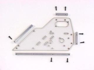 Figure 1. |
| Step 2.
Install 3 of the 1-1/2" spacers using 3 of the 4-40 x 5/8"
screws from the underside of the panel. The screws should thread into the
metal bars first, then pass through the Lexan panel. Note, this is
opposite of the previous step. When done correctly the spacers should be
sticking out on the side without the metal bars. Mirror for the right
side.
6 x |
 Figure 2. |
| Step 3.
Install 2 of the 1-1/2" spacers using 2 of the 4-40 x 3/8"
screws from the underside of the panel. The spacers should be sticking out
on the side without the metal bars. Mirror for the right side.
4 x |
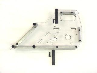 Figure 3. |
| Step 4.
Install the fender using 5 of the 4-40 x 3/8" screws as illustrated.
Mirror for the right side.
10 x |
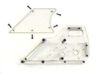 Figure 4. |
| Step 5.
Time to install the motors. Be sure the use the 3mm x 6mm screws, they're
the shiny ones with the Phillips head.
6 x |
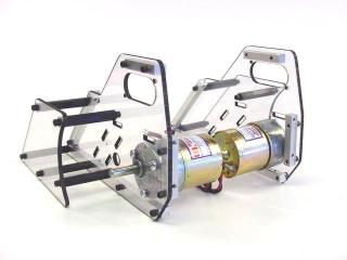 Figure 5. |
| Step 6. Solder the cap across the terminals as shown. Make sure you put the red to (+) and the black to (-). Use at least 20 awg stranded wire and cut to a length of about 6". | 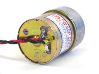 Figure 6. |
| Step 7.
Align the two halves of the robot as shown and install the bottom panel
using 6 of the 4-40 x 3/8" button head screws. Note, these screws
have a low profile head and are used here to prevent catching on the ring
edge. Take it easy on these, as they can be difficult to remove if
over-tightened.
6 x |
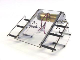 Figure 7. |
| Step 8. Insert the inside front shelf. If you are using one or two battery packs, use the front-most shelf holes, as is shown in Figure 8. If you are using three battery packs, use the rear set of shelf holes, closer to the motors. | 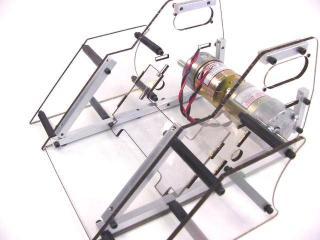 Figure 8. |
| Step 9.
Insert the inside top shelf.
Note: Remove the inner panel on the shelf, specifically when using the DHB motor driver and OOPic-R. It can also be left in for a solid shelf to hold an RC receiver. |
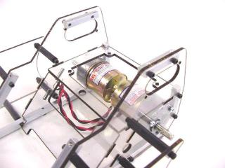 Figure 9. |
| Step 10.
Install the back panel using 4 of the 4-40 x 3/8" button head screws.
These are used here to minimize the robots total length.
4 x |
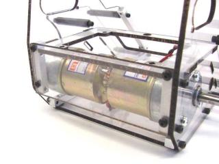 Figure 10. |
| Step 11.
Install the scoop using 4 of the 4-40 x 3/8" button head screws.
4 x |
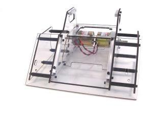 Figure 11. |
| Step 12.
Install the top panel using 4 of the 4-40 x 3/8" screws.
4 x |
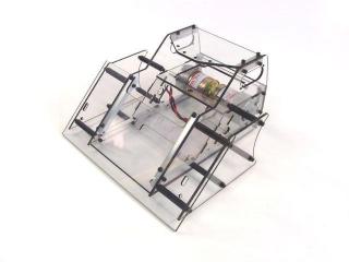 Figure 12. |
| Step 13.
Install the wheels. First put the set screw into the aluminum hub. Align
the set screw over the flat on the shaft. Tighten until it touches then
slide the hub as far as in a possible. Then torque it down tight. Install
the wheels onto the hubs using the 5-40 x 5/8" screws. Careful, you
can over do it on these.
4 x |
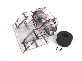 Figure 13. |
| Step 14. This completes the assembly of the rolling chassis. You will need improve the edge of the scoop where it meets the surface of the Sumo ring. This can be done in many ways, so I will leave it to your imagination. Remember, most Sumo wins occur when the robot gets under the opponent's scoop. | 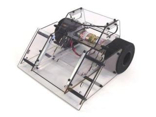 Figure 14. |