LSS - Communication Protocol
Page Contents
Serial Protocol
The Lynxmotion Smart Servo (LSS) serial protocol was created in order to be as simple and straightforward as possible from a user perspective ("human readable format"), while at the same time staying compact and robust yet highly versatile. The protocol was based on Lynxmotion's SSC-32 & SSC-32U RC servo controllers and almost everything one might expect to be able to configure for a smart servomotor is available.
In order to be able to control each servo individually with commands, the first step should be to assign a different ID number to each servo (see details on the Configure ID, or "CID" command here). Only the servo(s) which have been configured to a specific ID will act on a command sent to that ID. There is currently no CRC or checksum implemented as part of the protocol.
Session
Action Commands
- Start with a number sign # (Unicode Character: U+0023)
- Servo ID number as an integer (assigning an ID described below)
- Action command (one or more letters, no whitespace, capital or lowercase from the list below)
- Action value in the correct units with no decimal
- End with a carriage return \r or <cr> Unicode Character (U+000D)
Modifiers
- Start with a number sign # (Unicode Character: U+0023)
- Servo ID number as an integer
- Action command (one to three letters, no spaces, capital or lowercase from a subset of action commands below)
- Action value in the correct units with no decimal
- Modifier command (one or two letters from the list of modifiers below)
- Modifier value in the correct units with no decimal
- End with a carriage return \r or <cr> Unicode Character (U+000D)
Query Commands
- Start with a number sign # (Unicode Character: U+0023)
- Servo ID number as an integer
- Query command (one to four letters, no spaces, capital or lower case)
- End with a carriage return \r or <cr> Unicode Character (U+000D)
- Start with an asterisk * (Unicode Character: U+0023)
- Servo ID number as an integer
- Query command (one to four letters, no spaces, capital letters)
- The reported value in the units described, no decimals.
- End with a carriage return \r or <cr> Unicode Character (U+000D)
Configuration Commands
- Start with a number sign # (Unicode Character: U+0023)
- Servo ID number as an integer
- Configuration command (two to four letters, no spaces, capital or lower case)
- Configuration value in the correct units with no decimal
- End with a carriage return \r or <cr> Unicode Character (U+000D)
Virtual Angular Position
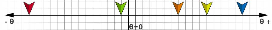 In this example, the gyre direction (explained below, a.k.a. "rotation direction") is positive (clockwise), and origin offset has not been modified. Each square represents 30 degrees. The following command is sent:#1D-300<cr> This causes the servo to move to -30.0 degrees (green arrow)#1D2100<cr> This second position command is sent to the servo, which moves it to 210.0 degrees (orange arrow)#1D-4200<cr> This next command rotates the servo counterclockwise to a position of -420 degrees (red arrow), which means one full rotation of 360 degrees plus 60.0 degrees (420.0 - 360.0), with a virtual position of -420.0 degrees. Although the final physical position would be the same as if the servo were commanded to move to -60.0 degrees, the servo is in fact at -420.0 degrees. #1D4800<cr> This new command is sent which would then cause the servo to rotate from -420.0 degrees to 480.0 degrees (blue arrow), which would be a total of 900 degrees of clockwise rotation, or 2.5 complete rotations. #1D3300<cr> would cause the servo to rotate from 480.0 degrees to 330.0 degrees (yellow arrow).If the servo loses power or is power cycled, it also loses the virtual position associated with that session. For example, if the virtual position was 480.0 degrees before power is cycled, upon power up the servo's position will be read as +120.0 degrees from zero (assuming center position has not been modified). The virtual position range at power-up is [-180.0°, 180.0°].
Command List
Latest firmware version currently : 368.29.14
| Communication Setup | |||||||||
| Description | Action | Query | Config | RC | Serial | Default | Unit | Notes | |
| Reset | RESET | ✓ | Soft reset. See command for details. | ||||||
| Default Configuration | DEFAULT | ✓ | Revert to firmware default values. See command for details | ||||||
| Firmware Update Mode | UPDATE | ✓ | Update firmware. See command for details. | ||||||
| Confirm Changes | CONFIRM | ✓ | |||||||
| Change to RC | CRC | ✓ | Change to RC mode 1 (position) or 2 (wheel). | ||||||
| ID # | QID | CID | ✓ | 0 | Reset required after change. ID 254 is a "broadcast" which all servos respond to. | ||||
| Baudrate | QB | CB | ✓ | 115200 | Reset required after change. | ||||
| Motion | |||||||||
| Description | Action | Query | Config | RC | Serial | Default | Unit | Notes | |
| Position in Degrees | D | QD/QDT | ✓ | 1/10° | |||||
| Move in Degrees (relative) | MD | ✓ | 1/10° | ||||||
| Wheel mode in Degrees | WD | QWD/QVT | ✓ | °/s | A.K.A. "Speed mode" or "Continuous rotation" | ||||
| Wheel mode in RPM | WR | QWR | ✓ | RPM | A.K.A. "Speed mode" or "Continuous rotation" | ||||
| Position in PWM | P | QP | ✓ | us | Inherited from SSC-32 serial protocol | ||||
| Move in PWM (relative) | M | ✓ | us | ||||||
| Raw Duty-cycle Move | RDM | QMD | ✓ | -1023 to 1023 integer | Positive values : CW / Negative values : CCW | ||||
| Query Status | Q | ✓ | 1 to 8 integer | See command description for details | |||||
| Limp | L | ✓ | |||||||
| Halt & Hold | H | ✓ | |||||||
| Motion Setup | |||||||||
| Description | Action | Query | Config | RC | Serial | Default | Unit | Notes | |
| Enable Motion Profile | EM | QEM | CEM | ✓ | 1 | EM1: trapezoidal motion profile / EM0: no motion profile | |||
| Filter Position Count | FPC | QFPC | CFPC | ✓ | ✓ | 5 | Affects motion only when motion profile is disabled (EM0) | ||
| Origin Offset | O | QO | CO | ✓ | ✓ | 0 | 1/10° | ||
| Angular Range | AR | QAR | CAR | ✓ | ✓ | 1800 | 1/10° | ||
| Angular Stiffness | AS | QAS | CAS | ✓ | ✓ | 0 | -4 to +4 integer | Suggested values are between 0 to +4 | |
| Angular Holding Stiffness | AH | QAH | CAH | ✓ | ✓ | 4 | -10 to +10 integer | ||
| Angular Acceleration | AA | QAA | CAA | ✓ | 100 | °/s2 | Increments of 10°/s2. Only when motion profile is enabled (EM1). | ||
| Angular Deceleration | AD | QAD | CAD | ✓ | 100 | °/s2 | Increments of 10°/s2. Only when motion profile is enabled (EM1). | ||
| Gyre Direction | G | QG | CG | ✓ | ✓ | 1 | Gyre / rotation direction: 1= CW (clockwise) -1 = CCW (counter-clockwise) | ||
| First Position (Deg) | QFD | CFD | ✓ | ✓ | No value | 1/10° | Reset required after change. | ||
| Maximum Motor Duty | MMD | QMMD | ✓ | 1023 | 255 to 1023 integer | ||||
| Maximum Speed in Degrees | SD | QSD | CSD | ✓ | ✓ | Max | 0.1°/s | SD overwrites SR / CSD overwrites CSR and vice-versa | |
| Maximum Speed in RPM | SR | QSR | CSR | ✓ | ✓ | Max | RPM | SD overwrites SR / CSD overwrites CSR and vice-versa | |
| Modifiers | |||||||||
| Description | Modifier | Query | Config | RC | Serial | Default | Unit | Notes | |
| Speed | S | QS | ✓ | uS/s | For P action command | ||||
| Speed in Degrees | SD | ✓ | 0.1°/s | For D and MD action commands | |||||
| Timed move | T | ✓ | ms | Modifier only for P, D and MD. Time can change based on load | |||||
| Current Hold | CH | ✓ | mA | Modifier for D, MD, WD and WR | |||||
| Current Limp | CL | ✓ | mA | Modifier for D, MD, WD and WR | |||||
| Telemetry | |||||||||
| Description | Action | Query | Config | RC | Serial | Default | Unit | Notes | |
| Query Voltage | QV | ✓ | mV | ||||||
| Query Temperature | QT | ✓ | 1/10°C | ||||||
| Query Current | QC | ✓ | mA | ||||||
| Query Model String | QMS | ✓ | Returns the model of servo (ex: LSS-ST1, LSS-HS1, LSS-HT1) | ||||||
| Query Firmware Version | QF | ✓ | |||||||
| Query Serial Number | QN | ✓ | Returns the unique serial number for the servo | ||||||
| RGB LED | |||||||||
| Description | Action | Query | Config | RC | Serial | Default | Unit | Notes | |
| LED Color | LED | QLED | CLED | ✓ | ✓ | 0 to 7 integer | 0=Off; 1=Red; 2=Green; 3=Blue; 4=Yellow; 5=Cyan; 6=Magenta; 7=White | ||
| Configure LED Blinking | CLB | ✓ | ✓ | 0 to 63 integer | Reset required after change. See command for details. | ||||
Details
Communication Setup
Reset
Default & confirm
Update & confirm
Confirm
Configure RC Mode (CRC)
| Command sent | Note |
| ex: #5CRC1<cr> | Change to RC position mode. |
| ex: #5CRC2<cr> | Change to RC continuous rotation (wheel) mode. |
| ex: #5CRC*<cr> | Where * is any value other than 1 or 2 (or no value): stay in smart mode. |
Identification Number (ID)
Baud Rate
Automatic Baud Rate
Motion
Position in Degrees (D)
(Relative) Move in Degrees (MD)
Wheel Mode in Degrees (WD)
Wheel Mode in RPM (WR)
Position in PWM (P)
(Relative) Move in PWM (M)
Raw Duty-cycle Move (RDM)
Query Status (Q)
| *Value returned (Q) | Status | Detailed description | |
| ex: *5Q0<cr> | 0: Unknown | LSS is unsure / unknown state | |
| ex: *5Q1<cr> | 1: Limp | Motor driving circuit is not powered and horn can be moved freely | |
| ex: *5Q2<cr> | 2: Free moving | Servo is rotating in duty motion / free move using the RDM command | |
| ex: *5Q3<cr> | 3: Accelerating | Increasing speed from rest (or previous speed) towards travel speed | |
| ex: *5Q4<cr> | 4: Traveling | Moving at a stable speed | |
| ex: *5Q5<cr> | 5: Decelerating | Decreasing from travel speed towards final position. | |
| ex: *5Q6<cr> | 6: Holding | Keeping current position (in EM0 mode, return will nornally be holding) | |
| ex: *5Q7<cr> | 7: Outside limits | {More details coming soon} | |
| ex: *5Q8<cr> | 8: Stuck | Motor cannot perform request movement at current speed setting | |
| ex: *5Q9<cr> | 9: Blocked | Similar to stuck, but the motor is at maximum duty and still cannot move (i.e.: stalled) | |
| ex: *5Q10<cr> | 10: Safe Mode | A safety limit has been exceeded (temperature, peak current or extended high current draw). Send a Q1 command to know which limit has been reached (described below). |
| *Value returned (Q1) | Status | Detailed description | |
| ex: *5Q0<cr> | No limits have been passed | Nothing is wrong | |
| ex: *5Q1<cr> | Current limit has been passed | Something cause the current to either spike, or remain too high for too long | |
| ex: *5Q2<cr> | Input voltage detected is below or above acceptable range | Check the voltage of your batteries or power source | |
| ex: *5Q3<cr> | Temperature limit has been reached | The servo is too hot to continue operating safely. |
Limp (L)
Halt & Hold (H)
Motion Setup
Enable Motion Profile (EM)
Filter Position Count (FPC)
Origin Offset (O)
 In the second image, the origin, and the corresponding angular range (explained below) have been shifted by +240.0 degrees:
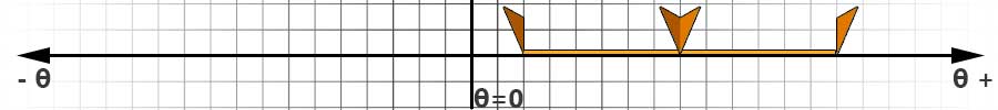 Origin Offset Query (QO)Example: #5QO<cr> might return *5QO-13This allows you to query the angle (in tenths of degrees) of the origin in relation to the factory zero position. In this example, the new origin is at -1.3 degrees from the factory zero.Configure Origin Offset (CO)Example: #5CO-24<cr>This command allows you to change the origin of the servo in relation to the factory zero position in EEPROM. The setting will be saved upon servo reset / power cycle. Origin offset configuration commands are not cumulative and always relate to factory zero. The new origin is also used in RC mode. In the example, the new origin will be at -2.4 degrees from the factory zero.
Angular Range (AR)
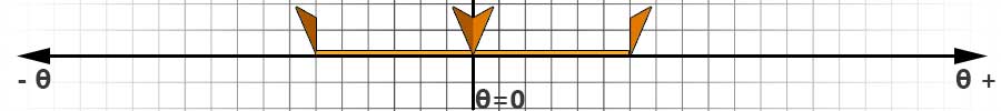
Below, the angular range is restricted to 180.0 degrees, or -90.0 to +90.0. The center has remained unchanged.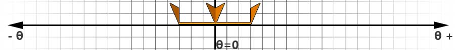 Finally, the angular range action command (ex. #5AR1800<cr>) and origin offset action command (ex. #5O-1200<cr>) are used to move both the center and limit the angular range:
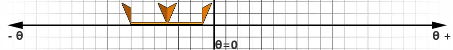 Query Angular Range (QAR)Example: #5QAR<cr> might return *5AR1800, indicating the total angular range is 180.0 degrees.Configure Angular Range (CAR)This command allows you to change the total angular range of the servo in tenths of degrees in EEPROM. The setting will be saved upon servo reset / power cycle.
Angular Stiffness (AS)
- The more torque will be applied to try to keep the desired position against external input / changes
- The faster the motor will reach its intended travel speed and the motor will decelerate faster and nearer to its target position
- Causes a slower acceleration to the travel speed, and a slower deceleration
- Allows the target position to deviate more from its position before additional torque is applied to bring it back
Angular Holding Stiffness (AH)
Angular Acceleration (AA)
Angular Deceleration (AD)
Gyre Direction (G)
First Position
Maximum Motor Duty (MMD)
Maximum Speed in Degrees (SD)
| Command sent | Returned value (1/10 °) |
| ex: #5QSD<cr> | Session value for maximum speed (set by latest SD/SR command) |
| ex: #5QSD1<cr> | Configured maximum speed in EEPROM (set by CSD/CSR) |
| ex: #5QSD2<cr> | Instantaneous speed (same as QWD) |
| ex: #5QSD3<cr> | Target travel speed |
Maximum Speed in RPM (SR)
| Command sent | Returned value (1/10 °) |
| ex: #5QSR<cr> | Session value for maximum speed (set by latest SD/SR command) |
| ex: #5QSR1<cr> | Configured maximum speed in EEPROM (set by CSD/CSR) |
| ex: #5QSR2<cr> | Instantaneous speed (same as QWD) |
| ex: #5QSR3<cr> | Target travel speed |
Modifiers
Speed (S, SD) modifier
Timed move (T) modifier
Current Halt & Hold (CH) modifier
Current Limp (CL) modifier
Telemetry
Query Voltage (QV)
Query Temperature (QT)
Query Current (QC)
Query Model String (QMS)
Query Firmware (QF)
Query Serial Number (QN)
RGB LED
LED Color (LED)
Configure LED Blinking (CLB)
| Blink While: | # |
| No blinking | 0 |
| Limp | 1 |
| Holding | 2 |
| Accelerating | 4 |
| Decelerating | 8 |
| Free | 16 |
| Travelling | 32 |
| Always blink | 63 |
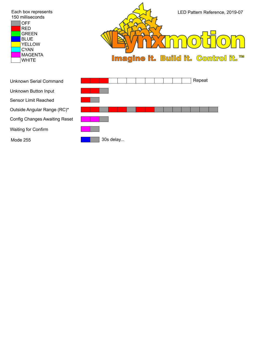
RGB LED Patterns
The LED patterns below do not include those which are part of the button menu, which can be found here: LSS Button Menu