
LSS Radio Control (PWM)
Page Contents
- RC Pulse Width Modulation (PWM)
- Lynxmotion Smart Servo (LSS) RC Modes
- Wiring
- Programmable Functionality
RC Pulse Width Modulation (PWM)
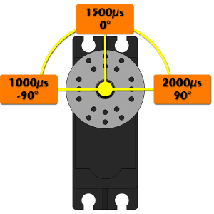
RC hobby servo motors have three pins; the black wire is ground (GND), the middle (red) wire is VCC (normally 4.8V to 6V) and the last wire (commonly yellow or white) is the signal wire. The signal wire is meant to receive 5V PWM pulses which are repeated every 20-30 milliseconds. The onboard electronics receive and time these pulses and associate them to angular positions. If no RC pulse is received, the servo goes limp. All RC servos are centered at 1500 microseconds, and 1000 microseconds tends to correspond to -90 degrees, and 2000 microseconds to +90 degrees. Note that by default many handheld RC transmitters only send between 600 to 2400 microseconds (slightly limited range). Pulses which cannot be interpreted by the servo (ex. constant LOW or HIGH) may cause the servo to go limp.
Lynxmotion Smart Servo (LSS) RC Modes
All three Lynxmotion Smart Servo motors can be used with normal hobby remote control (RC) electronics including handheld remote controls and RC servo controllers. Unlike normal RC servo motors however, the Lynxmotion servo's configurations can be changed via programming. There are two methods to change from serial to RC mode: via the LSS - Button Menu or sending a CRC command (explained on the communication protocol page). Note: Each mode can have the rotation reversed, but clockwise is standard (equivalent to CW1 or CW-1 commands). The motion controller used in serial mode is not the same as the motion controller use in RC mode. RC mode is intended to add functionality to what would be considered "normal" RC behavior based on PWM input.
180° Mode
This means a range of -90.0 degrees to +90.0 degrees (equivalent to sending a "configure angular range of 1800" or "CAR1800<cr>" command).


360° Mode
This gives a rotation angle of -180.0 to + 180.0 degrees or a full 360 degrees of rotation (equivalent to sending CAR 3600).

Wheel / Continuous Mode
Wheel mode is where a centered pulse of 1500 represents stop, and increasing the pulse towards 2500 increases the speed (for example CW), whereas decreasing the speed towards 500 increases the speed in the opposite direction (ex. CCW).

Wiring
When in RC mode, only one connector should be attached, and either connector on the servo can be used. The servo cannot be daisy-chained. The RC adapter cable includes the fourth pin connected as the cable can also be used to with non-RC electronics like FPGA boards and microcontrollers. In RC mode, the servo does not transmit any data on its TX pin (green wire).

Programmable Functionality
The functionality listed below applies to RC mode and can only via serial configuration commands. This means the servo must be connected to a computer (or other device like a microcontroller able to communicate serially) and the servo set to serial mode via the button menu. A detailed explanation of each command can be found on the LSS - Communication Protocol page; under the Command List, any configurations which has a checkmark associated with RC is included in RC mode. These configurations are saved within the servo and are retained even if the servo loses power.
Config. Origin Offset (CO): This command allows you to change the origin of the servo in relation to the factory zero position. The servo is shipped with the zero being centered on the side of the servo with the LED bar (image below)
Config. Angular Range (CAR): This is the total travel of the servo which is used in RC mode. The units are in tenths of degrees. The minimum value is 1 (0.1 degrees, which is essentially useless) up to 3600 (360.0 degrees). Note that 3600 represents the total travel, which can be interpreted as 360.0 degrees or ± 180.0 degrees where the center is in relation to the origin offset above.
Config. Max Speed (CSR, SDR): This sets the maximum speed in wheel mode (specified in either tenths of degrees per second or in rpm) corresponding to a pulse of either 500 microseconds or 2500 microseconds, with 1500 microseconds as "stopped". Note that the set speed cannot be above that of the servo's maximum.
Configure First position (CFP, CFD): This feature allows you to specify a startup position in either tenths of degrees (in relation to the factory origin) or as a pulse. By default the servo will not move at power-up until a signal is sent.
Config. LED Color (CLED): You can set the default color of the RGB LED when in use. This is purely aesthetic.
Config. Direction of rotation (CG): In certain applications, it is preferably to reverse the direction of the servo in relation to the pulse. See images below.
Examples:
With the "Angular Range" set 240.0° (±120.0°; CAR2400) of movement with the same 500µs to 2500µs signal.

With the "Angular Range" set to 240.0° (±120°; CAR2400) and "Origin Offset" you can shift the center position and still get your 240.0° range.

It is also possible to setup pass the 360.0° mark like here for a 720° (±360°; CAR7200) total rotation.

Important note
To revert from RC mode back to serial mode, the LSS - Button Menu is required. Should the button be inaccessible (or broken) when the servo is in RC mode and the user needs to change to serial mode, a 5V constant HIGH needs to be sent to the servo's Rx pin (RC PWM pin) with a common GND and wait for over 30 seconds. Normal RC PWM pulses should not exceed 2500 milliseconds. After 30 seconds, the servo will interpret this as a desired mode change and change to serial mode. This has been implemented as a fail safe.