LSS Electrical
Last modified by Eric Nantel on 2024/07/12 11:23
Page Contents
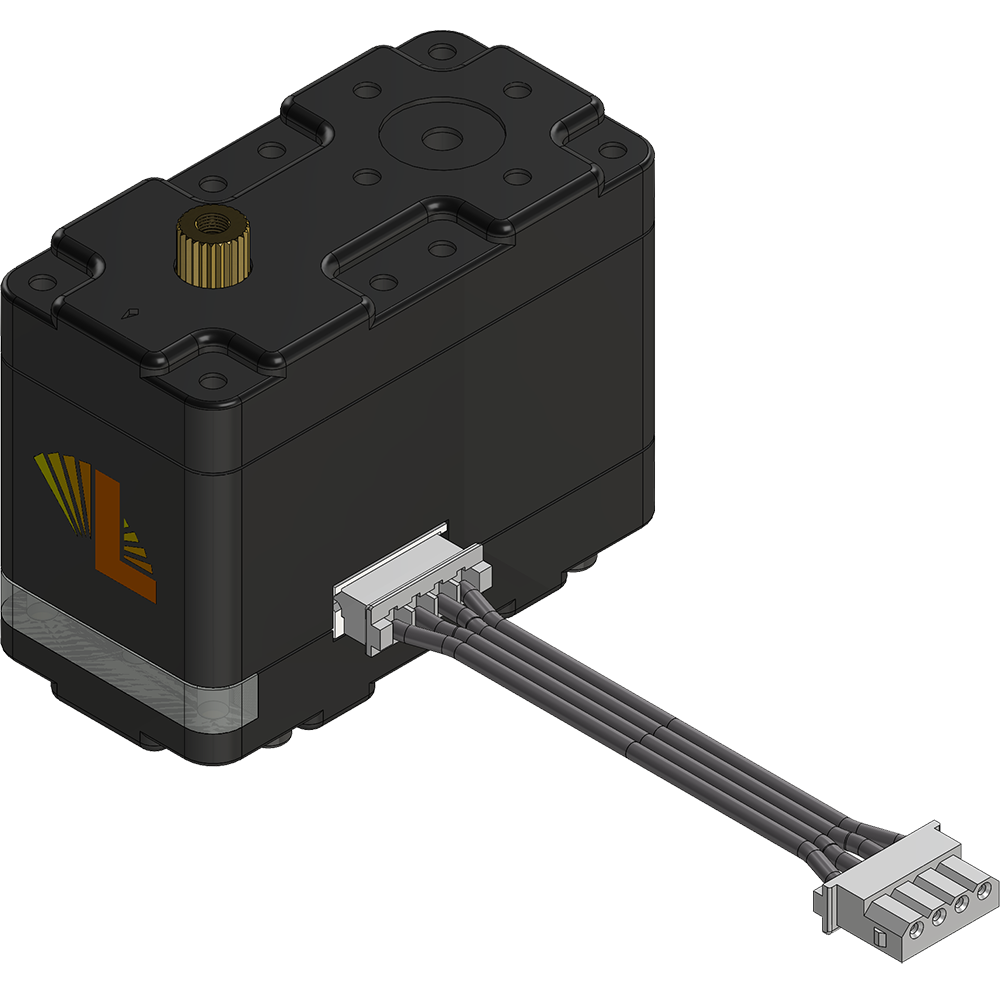
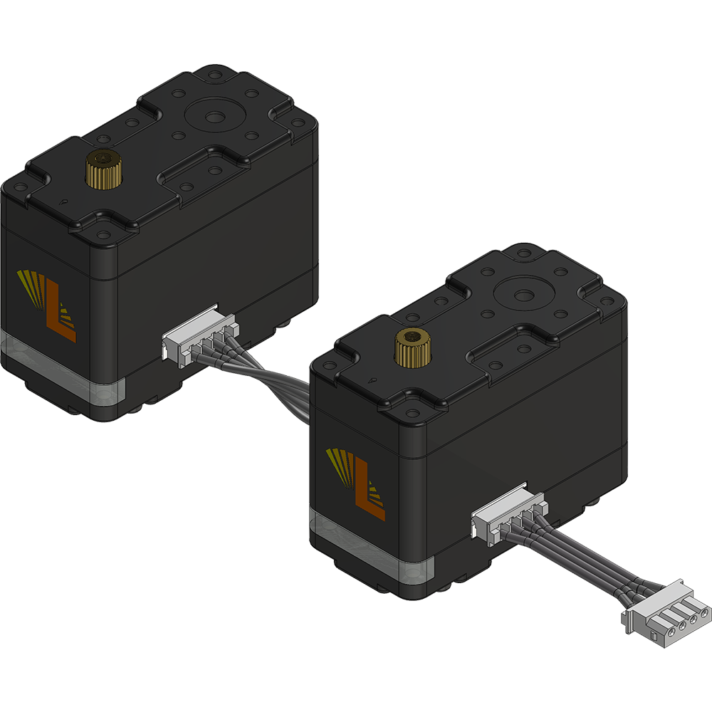
Typical Connections
In order to daisy chain one servo to the next (serial mode only), rollover serial cables are used. Although the wires are straight, one connector must be rotated 180 degrees with respect to the other.
| Serial Single | Serial Multiples | Radio Control (RC) | |
|
|
|
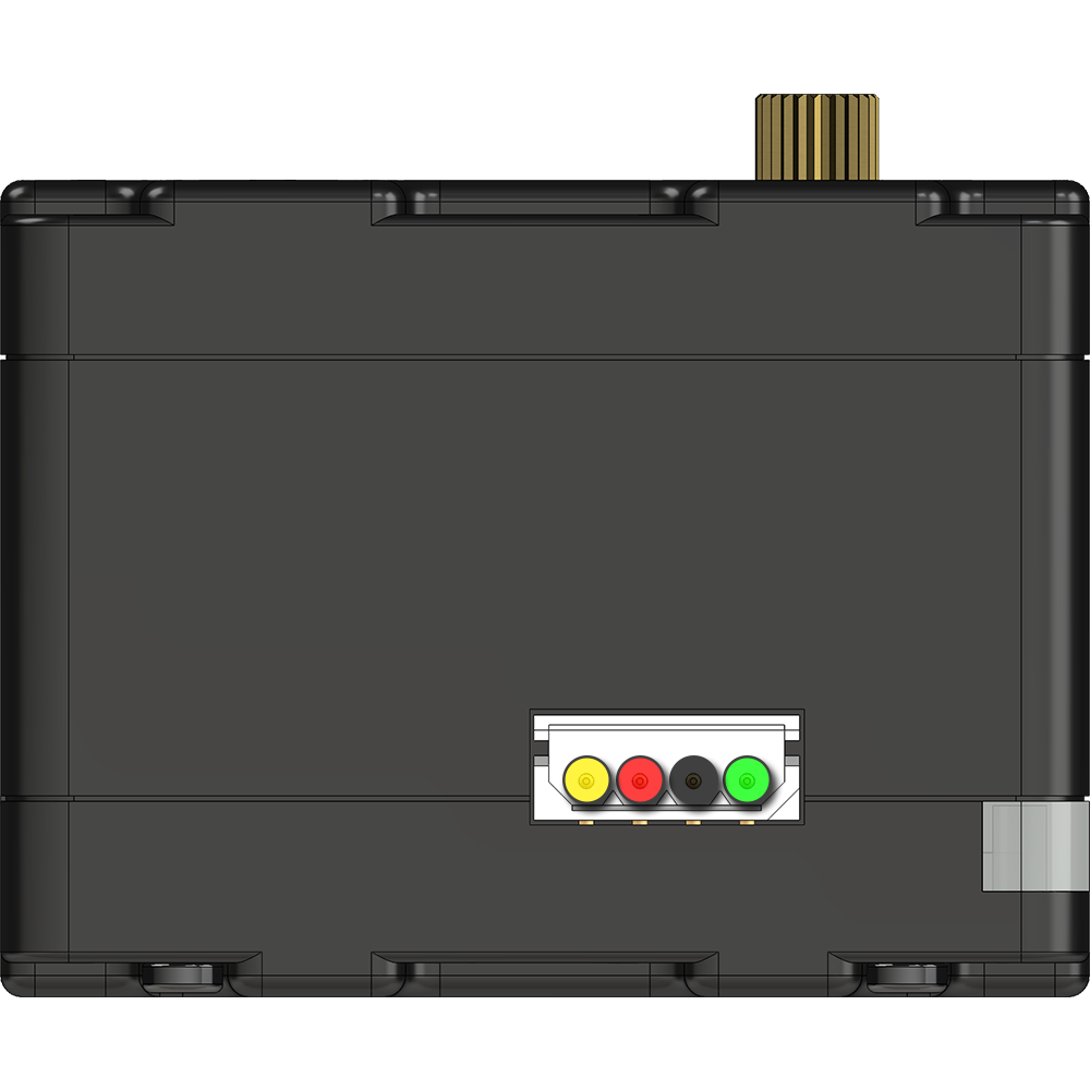
Wiring Pinout
| Serial Mode | RC Mode | ||
|  | Servo Rx: In serial mode, this pin should be connected to a 5V TTL serial pin. In RC mode, the pin should be connected to an 5V RC PWM pin | Servo RC Signal:Please refer to the LSS - RC PWM for more information regarding the RC mode and signals |
 | Servo Vcc: Refer to the Voltage section of the LSS - Specifications page to understand which voltages are meant to be connected to this pin. | Same as Serial Mode | |
 | Ground (GND): This pin should be connected to both the communication sources' ground, as well as that of the power source (principle of "common ground"). | Same as Serial Mode | |
 | Servo Tx: In serial mode, this pin sends the output from query commands. In RC mode, the cable does not need to be connected as there is no output. | N/A: Futur Implementation |
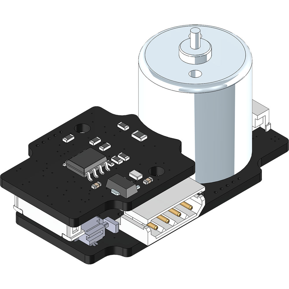
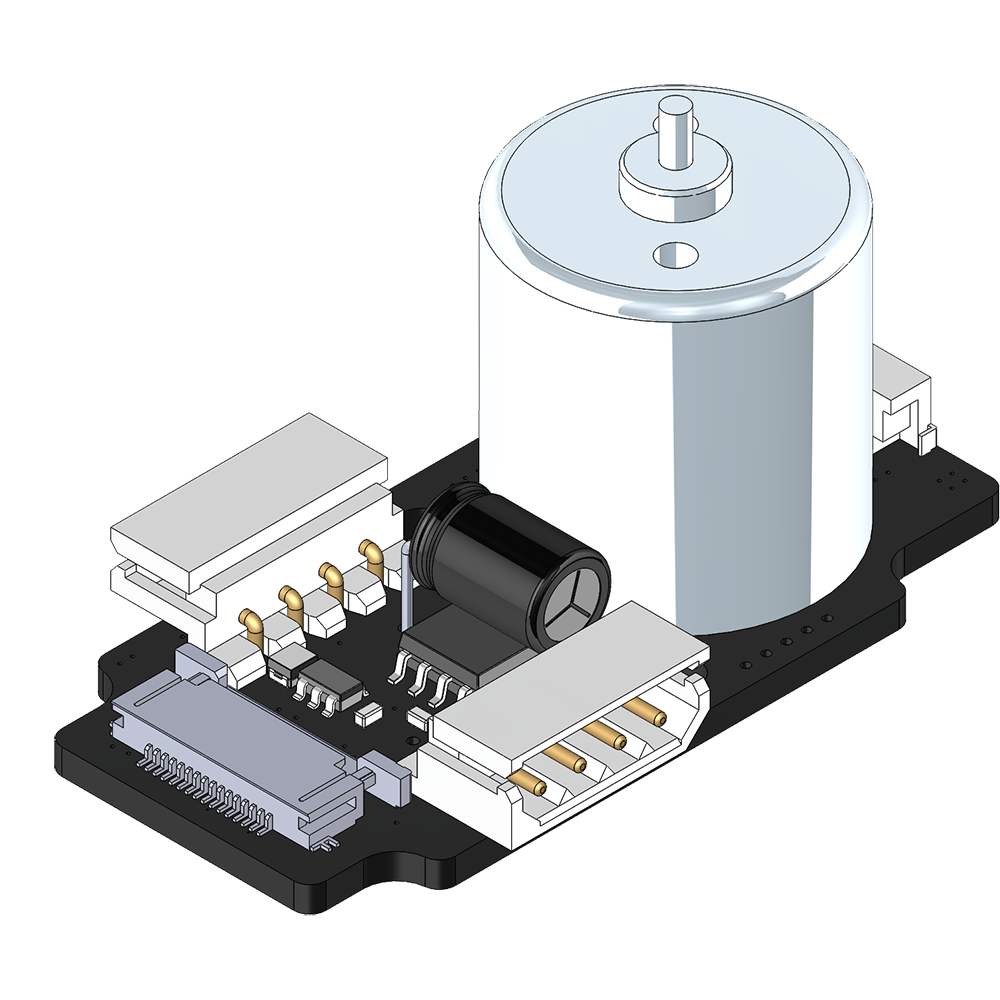
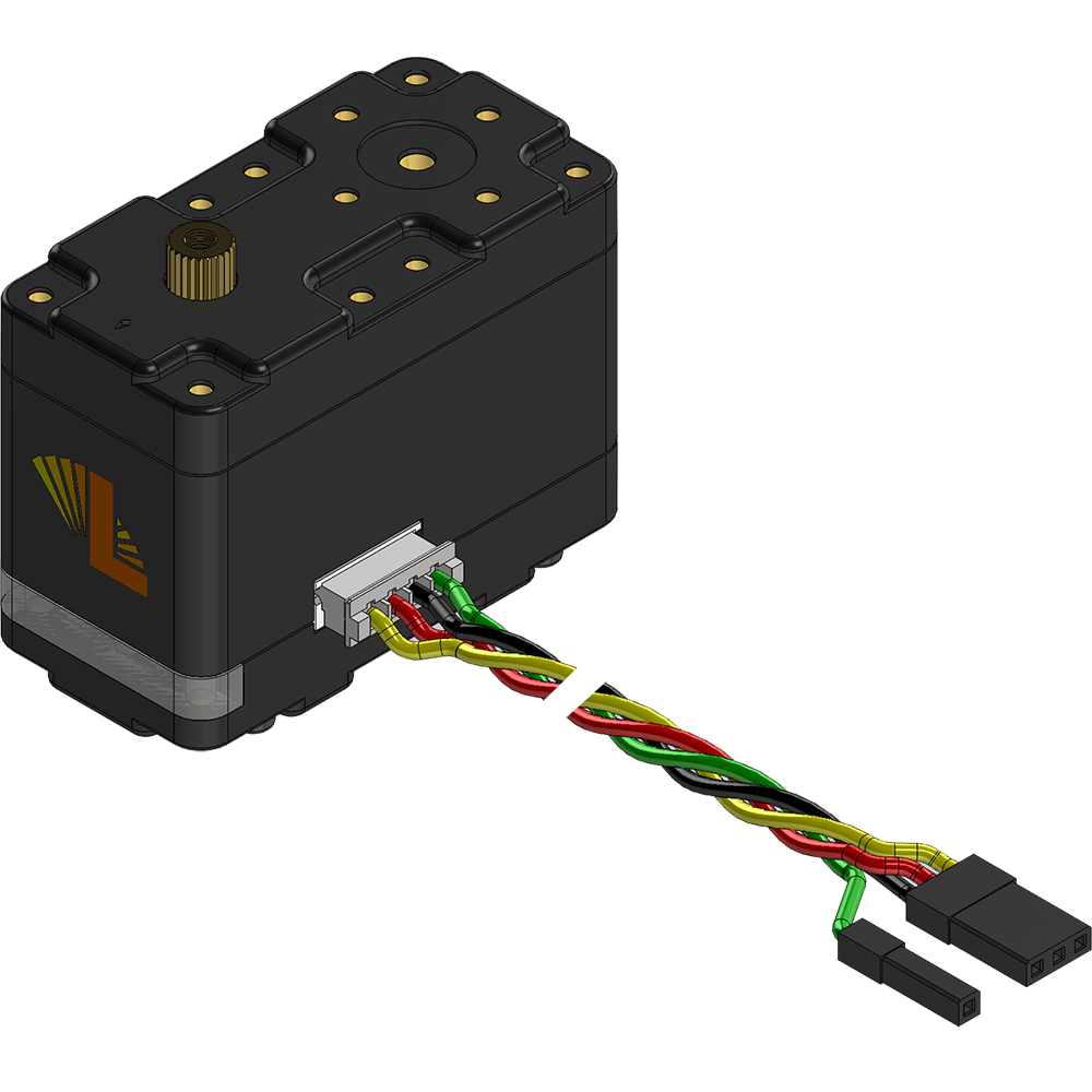
Electronics
|
| The electronics inside the servo include the following:
|