
MES - Power Distribution Board (PDB)
Page Contents
Description
*** READ THIS MANUAL, ESPECIALLY THE SAFETY SECTION BELOW BEFORE MAKING ANY CONNECTIONS***
The Multirotor Erector Set (MES) Power Distribution Board (PDB) is a highly versatile system; its two PCB design (separate positive and negative power planes), 4oz copper thickness and two battery inputs, allows it to easily power up to 8 UAV motors with a continuous current capacity of 20 amps each (160A total) and a peak / instantanous current capacity of 35A per motor (280A total). This PDB has also an onboard, internally driven buzzer and a pinout directly compatible with the Quadrino Nano Flight Controller.
Features
- Pinout compatible with the Lynxmotion Quadrino Nano Flight Controller, but can be used in any multirotor system
- Connect up to 8x motors using 3.5mm bullet connectors
- Positive and negative PCBs allow for high current
- Supports single or dual batteries setup
- Includes 1x XT60 to 3.5mm bullet connector battery cable adapter (additional cables sold separately).
- On-board internally driven buzzer
- Jumpers for battery elimination circuit (BEC) power management, battery monitoring and external device power selection
- Vin, GND and 5V pins broken out for the possibility of soldering an external 5V regulator
Specifications
- Continuous current of 20A per motor (160A total for 8 motors)
- Peak current of 35A (280A total for 8 motors) for several seconds
- Separate power PCBs : bottom PCB is connected to battery positive and top PCB is connected to battery negative
- 4oz copper thickness on both top and bottom PCBs
- 8 x 3.5mm male bullet connectors for ESCs positive leads + 2 x 3.5mm male bullet connectors for batteries positive leads
- 8 x 3.5mm female bullet connectors for ESCs negative leads + 2 x 3.5mm female bullet connectors for batteries negative leads
- On-board pre-amplified Buzzer : 5V 30mA 2.7kHz internally driven magnetic buzzer
Wiring
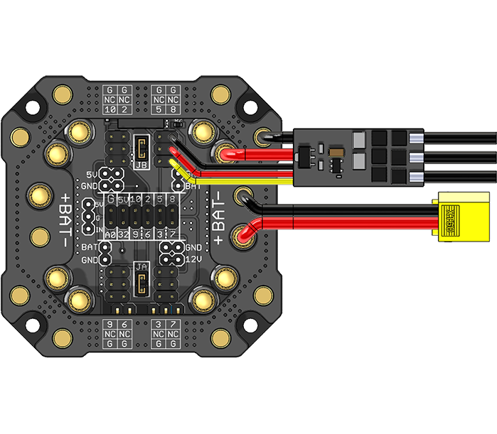
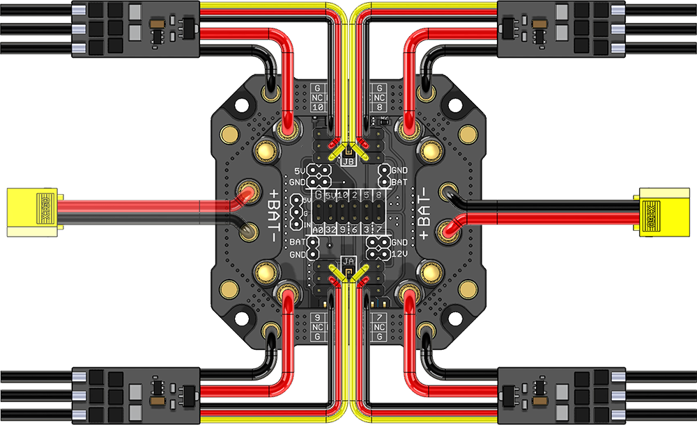
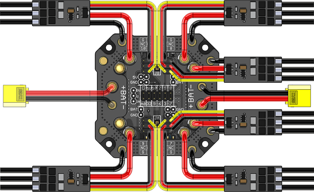
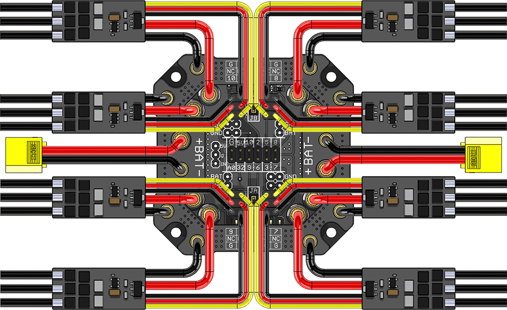
The wiring diagrams below show where to connect the XT60 battery wires, the ESCs power leads and RC wires for different copter types. Be sure to read the safety section below before making any connections.
- DO NOT connect the batteries until everything has been wired and checked.
- Verify the polarity of the battery connector(s) and sure the positive (red) lead connects to the top PCB, and the negative / GND (black) lead connects to the bottom PCB.
- Should your ESC not use the correct bullet connectors for power, the existing connectors can be removed and replaced by 3.5mm connectors.
- Connect the ESCs to the PDB based on the configurations below, ensuring the positive is connected to the top plate and negative connected to the bottom plate.
- For a single battery configuration, the ESCs should be installed close to the battery
- For a dual battery configuration, the ESCs should be installed equally on the board to try to lessen uneven current draw between the batteries
- Connect the three-pin cables based on your copter configuration below.
- When using two batteries, they should both be fully charged and provide the same output voltage. We suggest using two identical batteries from the same manufacturer.
- Ensure the battery or batteries selected can provide enough (discharge) current for all motors under load. Normally the discharge rating is provided as a C-rating.
- DO NOT remove any bullet connectors from the PDB when a battery is connected - disconnect the batteries first.
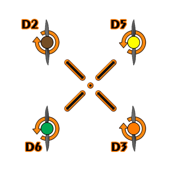
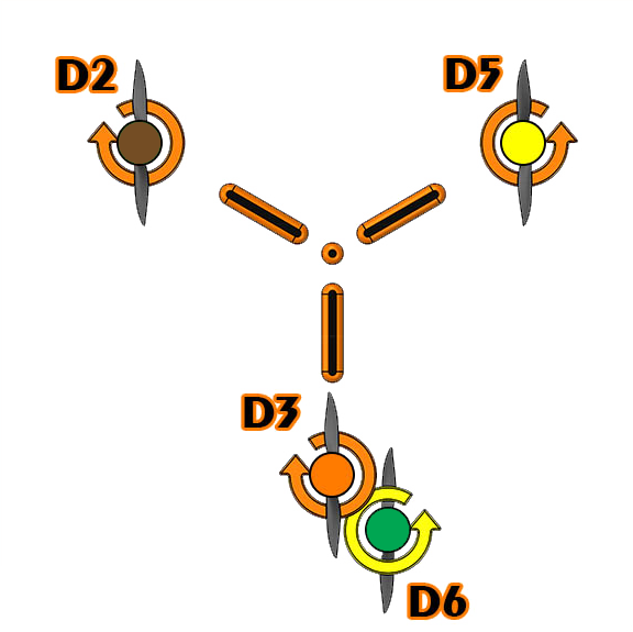
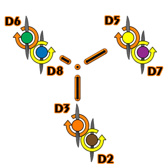
| 1x ESC | 4x ESCs | 6x ESCs | 8x ESCs |
|
|
|
|
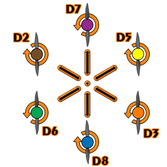
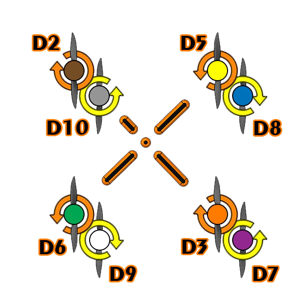
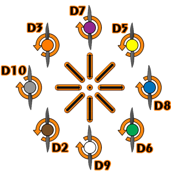
The following table shows the suggested connection points for each of the ESCs' power leads(positive and negative), their corresponding RC 3 pin connector and input signal pin based on the copter type :
 |  |  |  |  |  | ||
| ✓ | ✓ | |||||
| ✓ | ✓ | ✓ | ✓ | ✓ | ✓ | ||
| ✓ | ✓ | ✓ | ✓ | ✓ | ✓ | ||
| ✓ | ✓ | ✓ | ✓ | ||||
| ✓ | ✓ | ✓ | ✓ | ||||
| ✓ | ✓ | ✓ | ✓ | ✓ | ✓ | ||
| ✓ | ✓ | ✓ | ✓ | ✓ | ✓ | ||
| ✓ | ✓ | ||||||
 | 3.5mm Male Bullet Connector connected to the positive plane | ||||||
| 3.5mm Female Bullet Connector connected to the negative plane | |||||||
Jumpers
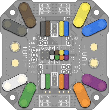
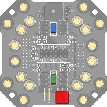
The MES PDB has three jumpers : JA, JB and Vout. The functionality of each jumper is explained below :
|
| JA jumper When installed, this jumper is intended to connect the battery's positive lead to the A0 pin to monitor the battery voltage on an analog input pin : | |||||
| JB jumper This jumper selects between the 5V input on the PDB (using an external, optional 5V regulator) or the BEC of ESC #2. With the jumper in place, the 5V line of the PDB is connected to the 5V BEC pin of ESC #2 (assuming the ESC includes a BEC) which will power all the 5V pins on the PDB. Note : Ensure to remove the JB jumper if a 5V external regulator is soldered on the PDB. | ||||||
| Vout jumper This jumper is intended to select between 5V provided by JB (from the optional, external 5V regulator or from the BEC of ESC #2, depending on the position of JB jumper) or use the main battery voltage (Vbat) on the Vout pin. The Vout pin is used along with D32 pin (active low) to power external devices (LEDs, Buzzer, etc.) : Jumper between Vout and 5V : external device connected to Vout and D32 will be 5V powered when D32 is low Note : Ensure to verify the rated voltage of the external device connected to D32 and Vout pins before inserting Vout jumper to 5V or BAT | ||||||
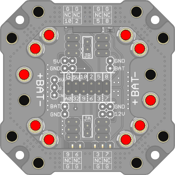
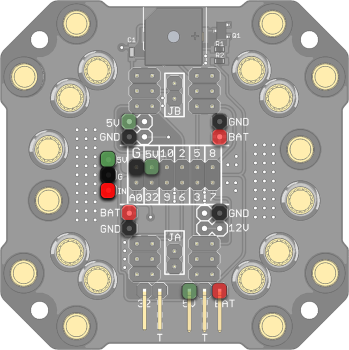
5V External Regulator
The MES PDB has 3 pins broken-out : BAT / Vin (Red), GND (Black) and 5V (Green) as indicated in the image below. The pinout is used to solder an optional, external 5V regulator (not included). Be sure to remove the JB jumper if an external 5V regulator is soldered to the PDB. Additional information regarding the optional Lynxmotion 5V and 12V regulators are provided here {coming soon}.
|
| 5V output of the external regulator which is connected to all 5V pins |
| GND pins | |
| Input voltage of the external regulator which is connected to the battery positive lead |
Quadrino Nano
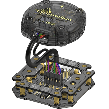
Although the MES PDB is intended to be used with any flight controller copter system, it was designed to be directly interfaced with the Lynxmotion Quadrino Nano Flight Controller.
| Using the appropriate wiring harness (QN-PDB-WH), the MES PDB can be connected to the Quadrino Nano via its middle 12 position, 2.54mm pitch connector as shown in this image. All RC signal pins from the ESCs connected to the PDB will be connected to the appropriate ESC inputs on the Quadrino Nano (refer to the wiring diagram above). The 5V pin (either from the optional, external 5V regulator or the BEC from ESC #2) on the PDB will power the Quadrino Nano. The A0 pin on the PDB takes advantage of the battery voltage monitoring feature on the Quadrino Nano (provided JA jumper is inserted). The D32 pin on the PDB will be driven by the Quadrino Nano (active low) to activate the on-board buzzer and any 5V/Battery Voltage (depending on the position of Vout jumper) external device connected to the PDB.
|
Thermal Analysis
Given the almost infinite number of potential situations regarding current draw, it is difficult to analyze all configurations. With this in mind, the following table summarizes the thermal analysis of the PDB when used with a single or dual battery drawing 160A or 280A continuous current.
| 160A Continunous (20A / ESC) | 280A Continuous (35A / ESC) | ||||
| Single Battery Input |  |  |  |  |
|
| Dual Battery Input |  |  |  |  | |
| TOP PCB | BOTTOM PCB | TOP PCB | BOTTOM PCB | ||

Dimensions
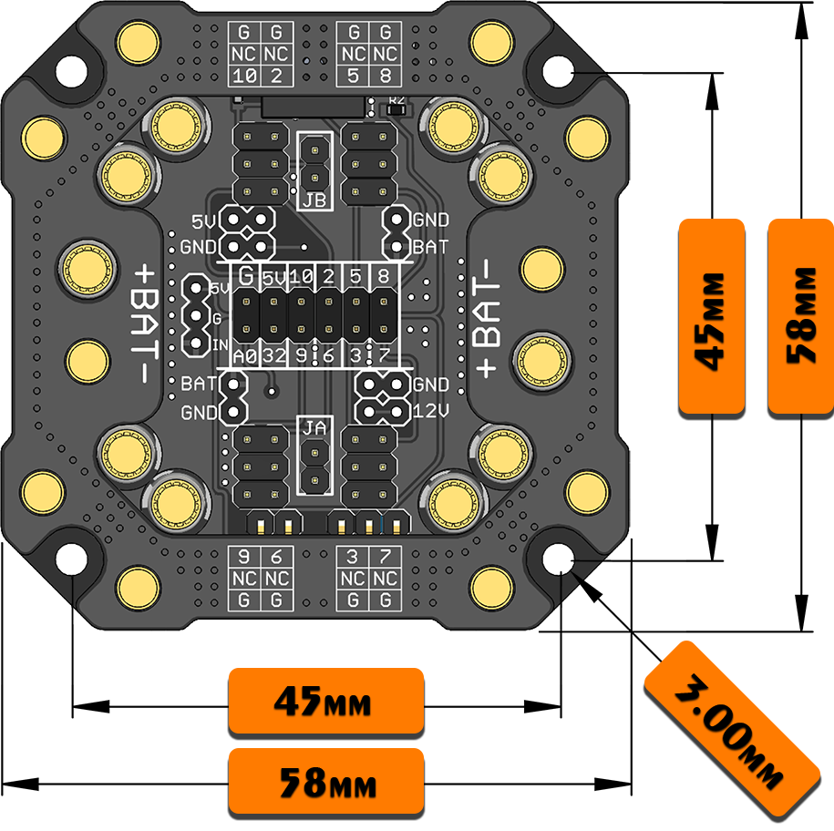 | The suggested mounting method for the PDB is using either standoffs or double-sided tape. Ensure there are no loose wires or connections which can contact the PDB and potentially cause a short circuit. |
Safety
Be sure to read through this guide and check all connections.
Warning: Double check the polarity of the XT60 battery wires and ESCs power leads
Warning: Ensure to connect the battery LAST
Warning: Pay attention to not short positive and negative bullet connectors accidently when the PDB is powered
Warning: Ensure the current draw from all motors does not exceed the maximum discharge current of the battery nor the PDB current rating
Warning: Ensure that JA jumper is not inserted if a 5V external regulator is soldered on the PDB
Warning: Verify the Vout jumper position before powering an external device through D32 and Vout