
Quadrapod Extreme Body Assembly Instructions Rev. 2
Extreme Quadrapod Body Assembly Guide — Rev. 2
Updated November 10, 2004
Safety first! Wear eye protection and never touch a powered robot!
Note: Do not use Loctite or thread locks on the assembly — they are not necessary and may cause damage to the Lexan.
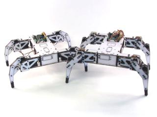
Completed Extreme Quadrapod.
Option A — Older kit (3/8" M/F + 1½" F/F spacers): Assemble the long spacers by threading the 3/8" M/F hex standoffs into the 1½" F/F spacers as shown, then proceed to Step 2.
Option B — Newer kit (1 7/8" F/F aluminum spacers): Skip this step and proceed directly to Step 2.
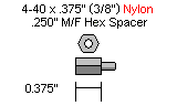
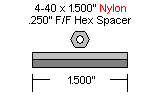
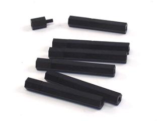 Figure 1.
Use ten 4-40 x 3/8" hex socket screws to attach the spacers to the underside of the top body panel.

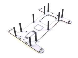 Figure 2.
To mount the Bot Board or OOPic-R, use four 3/8" nylon hex spacers and four 4-40 x 1/4" screws through the Lexan from bottom to top. Four additional 1/4" screws (included) are used to attach the board to the spacers.
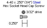
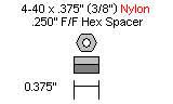
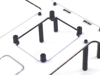 Figure 3.
If mounting an IRPD at the front of the robot, install two 3/8" spacers and two 4-40 x 1/4" screws now. Two additional 1/4" screws are used to attach the IRPD to the spacers.
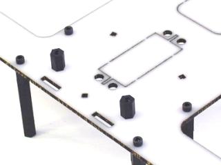 Figure 4.
Slide the end panels into position as shown. The panel with the servo hole is the front; the panel with the switch holes is the back.
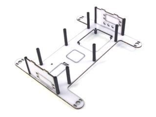 Figure 5.
Mount the bottom panel — note it is symmetrical with no front or back.
Option A (older kit — 3/8" M/F + 1½" F/F spacers): Use ten 4-40 x 1/4" hex screws.
Option B (newer kit — 1 7/8" F/F spacers): Use ten 4-40 x 3/8" hex screws.
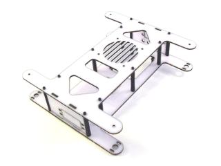 Figure 6.
Install the leg onto the robot base. To make this easier, pre-drill the indicated holes with a 1/16" drill bit. Use two #2 x 1/4" Phillips head tapping screws and two washers through the servo horn holes as shown.

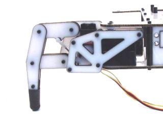 Figure 7-1.
Step 7-2: Make sure the leg lines up with the body as shown — correct alignment helps the robot walk straight.
Step 7-3: Install all four legs the same way, ensuring they all line up. This completes the mechanical assembly for the 2 DOF robot. See the Tutorials page for programming information.
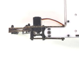 Figure 7-2 (alignment).
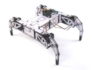 Figure 7-3 (all legs installed).
Newer kits include four black plastic side panels and eight extra body holes. Align the bottom of each panel in the bottom holes, routing the leg servo wires through the panel's hole, then press the top of the panel into place. To remove, press outward at the top of the panel.
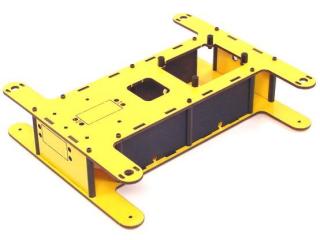 Figure 7-4.
Install the leg onto the robot base. Pre-drill the indicated holes with a 1/16" drill bit. Use two #2 x 1/4" Phillips head tapping screws and two washers through the servo horn holes as shown.
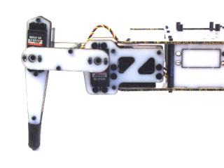 Figure 8-1.
Step 8-2: Make sure the leg lines up with the body as shown — correct alignment helps the robot walk straight.
Step 8-3: Install all four legs the same way, ensuring they all line up. This completes the mechanical assembly for the 3 DOF robot. See the Tutorials page for programming information.
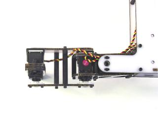 Figure 8-2 (alignment).
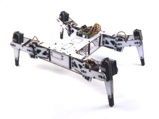 Figure 8-3 (all legs installed).
Newer kits include four black plastic side panels and eight extra body holes. Align the bottom of each panel in the bottom holes, routing the leg servo wires through the panel's hole, then press the top into place. To remove, press outward at the top of the panel.
Figure 8-4.