A4WD3-LED Board
Last modified by Eric Nantel on 2025/03/19 14:09
Table of Contents
Description
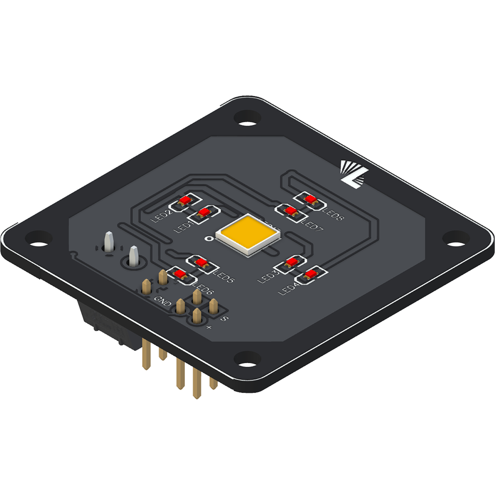
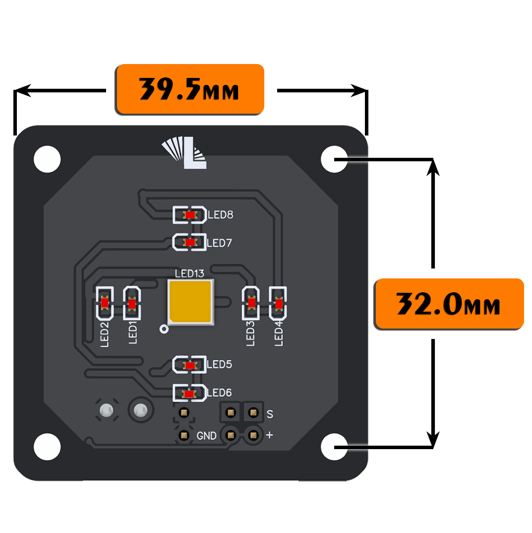
The Lynxmotion A4WD3 LED board was designed to be used within the frame of the Lynxmotion A4WD3 Rover, but can be used for all applications. The LEDs (white or all 8 red) can be controlled via power pins or using a microcontroller’s 5V digital pins. Includes mounting hardware.
Applications
- Lynxmotion A4WD3 front & back lighting
- Microcontroller-controlled robotic light
- Custom flashlight or bike light (front and rear)
Features
- Independant control over the White or Red LEDs
- Wide range of input voltage
- Screw terminal connection for input voltage.
Specifications
- 1x central white CREE LED (JR5050BWT)
- 8x Red 0630 LEDs
- Onboard voltage regulation
- Operating voltage: 10.5V min / 23V max
CAD Files
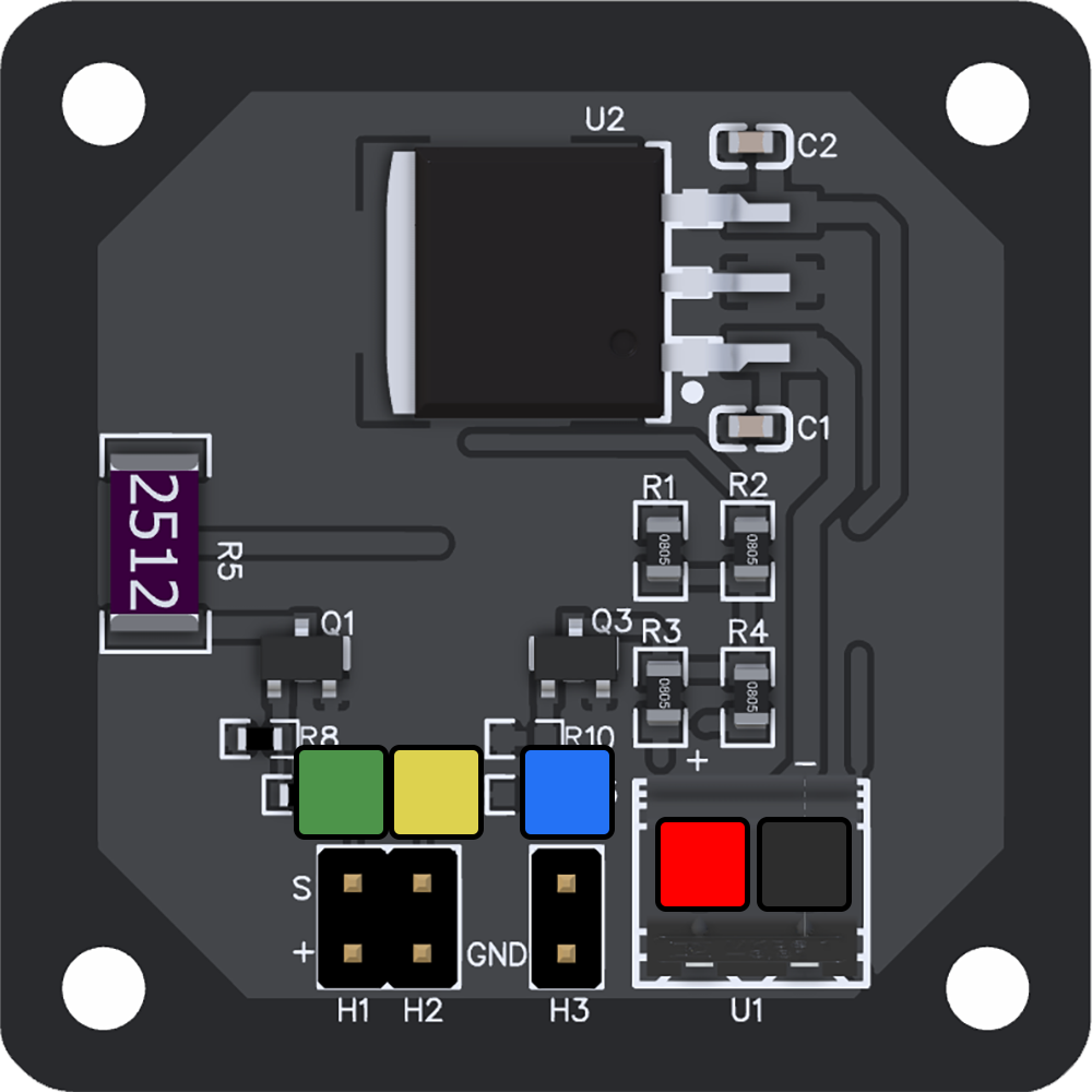
Pinout
 | Positive: Positive voltage Input (10.5V min / 23V max) | |
 | Negative: Negative voltage Input | |
 | Ground: Negative connection point to be used when a microcontroller control the LED's to be at the same potential. | |
 | H1 Jumper: Control for the CREE white LED
OR
| |
 | H2 Jumper: Control for the red LEDs
OR
|
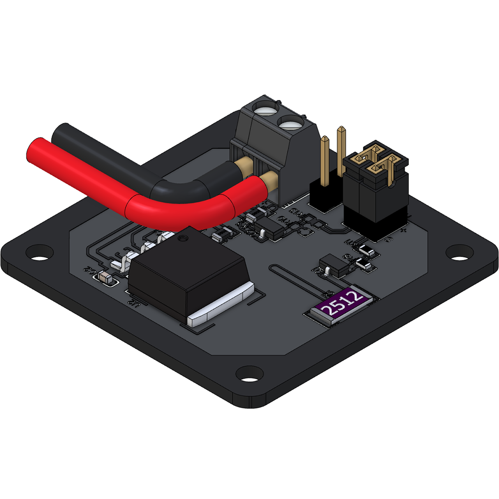
Wiring
| Jumpers | ||
 | Positive: Positive voltage Input (10.5V min / 23V max) | |
 | Negative: Negative voltage Input | |
 | Jumpers:
| |
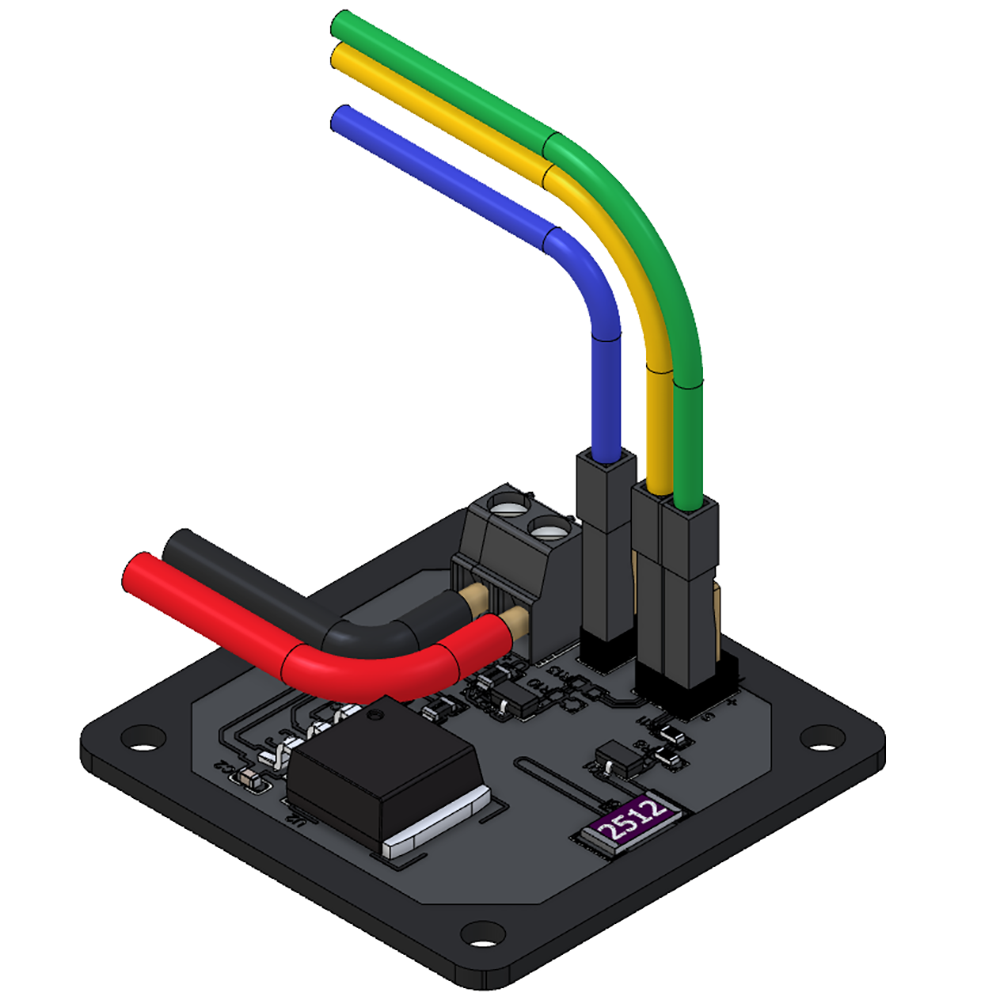
| Microcontroller | ||
 | Positive: Positive voltage Input (10.5V min / 23V max) | |
 | Negative: Negative voltage Input | |
 | Ground: Connect to the Negative or your Microcontroller | |
 | H1: Connect to a digital output (1.7V to 20V) to enable the CREE white LED Note: PWM compatible | |
 | H2: Connect to a digital output (1.7V to 20V) to enable the red LEDs Note: PWM compatible | |


