LSS-2IO Board

Table of Contents
- Description
- Features
- Specifications
- CAD Files
- Pinout
- Power
- Communication Modes
- Advanced Pinout
- Dimensions & Mounting
Description
The Lynxmotion LSS-2IO ("Lynxmotion Smart Servo To Input / Output") module was designed as a multi-purpose, Arduino programmable board intended to "bridge the gap" between a Lynxmotion Smart Servo (LSS) serial bus and regular 3-pin RC servos and 5V sensors. Although a default program is included when shipped, it can be re-programmed using the standard Arduino IDE software to communicate with digital, analog or I2C sensors acting as a standard Arduino board. It can also be used as a USB-to-Serial Adapter to directly control a Lynxmotion Smart Servo via USB.
Features
- Onboard switch to easily select between three communication modes
- USB Type-C connector (Earlier model was using USB Mini)
- 2x LSS connectors allow for daisy chaining
6x three row pins to easily connect 3-pin servos & sensors
- Digital pins : D9 / D10 / D11 (PWM capable)
- Analog & I2C pins : A3 / A4 (SDA) / A5 (SCL)
- Analog pins 5V rail and Logic 5V are separately powered by two on-board 5V regulators.
- LED (red): Tx-Rx USB serial activity (Tx & Rx)
- LED (green): Power LED (PWR)
- LED (RGB): Controlled by the user
- Arduino bootloader installed & Arduino IDE compatible
- Lynxmotion Smart Servo (LSS) mounting pattern
- Same form factor as the LSS - Power Hub
Specifications
- Microcontroller: ATMega328P
- USB-to-Serial IC: CH340E (Driver Download)
- Logic voltage: 5V
- Analog voltage rail: 5V
- Logic 5V maximum current: 200mA
- Analog 5V rail maximum current: 1.2A
- Number of analog pins: 3
- Number of digital IO pins: 3
- Input voltage via LSS connector: 6V-12V
- Maximum rated current through LSS connectors: 2A
- Default baud rate in 2RC mode (with LSS-2IO Arduino program pre-loaded): 115200
CAD Files
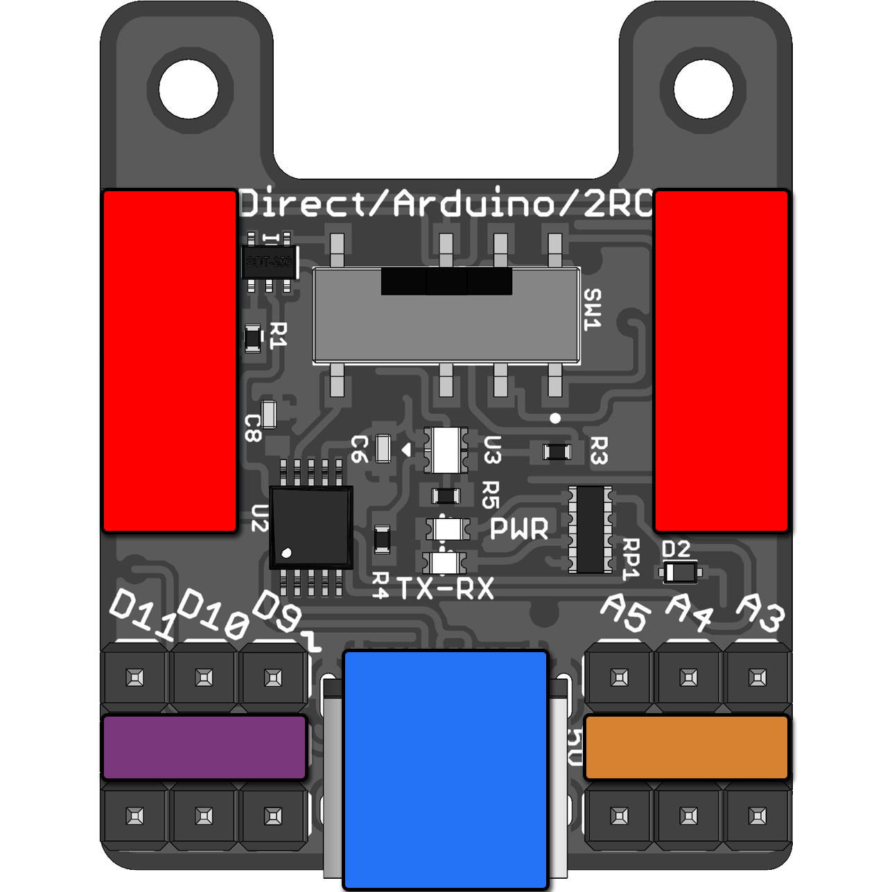
Pinout
External Pins & Connectors | ||
|  | Vin: Input voltage supplied by LSS bus (6V to ~12V). |
 | Ground (G): Common ground. | |
 | Vout: Output voltage from onboard 5VDC regulator. | |
 | LSS Rx | |
 | LSS Tx | |
 | 3x Digital Pins (D9, D10, D11): PWM Capable. | |
 | 3x Analog Pins (A3, A4, A5) | |
Internal Connections | ||
| | Pin D3: RGB LED red. |
| Pin D6: RGB LED green. | |
| Pin D5: RGB LED blue. | |
| Pin D14: Controls the tri-state buffer (IC3) on the ATMega328P Tx serial line (pulled-down). | |
| Pin D7: Controls the tri-state buffer (IC4) on CH340E Tx / ATMega328P Rx serial line (pulled-up). | |
Power
| | LSS Connectors: The board is meant to be powered from ONE of the two LSS connectors. Vin will supply the two on-board 5V regulators (logic and Vout) and to the Lynxmotion Smart Servos connected on the bus. Refer to LSS Voltage rating in LSS - Specifications |
| USB: Connecting only the USB will only provide voltage to the logic. It won't power Vout rail nor LSS connected on the bus. | |
| Vout: Output voltage rail from onboard 5VDC regulator. Intended to supply sensors requiring low current. | |
| Digital Pin Supply: This rmiddle rail need to be powered from an external power supply depending on what device is connected to the digital pins. LSS 5VR Board could be used to supply 5V/2A. |
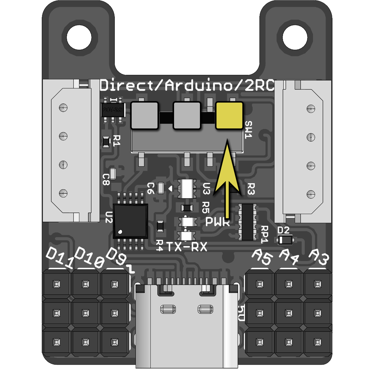
Communication Modes
The LSS 2IO Board has three serial communication modes which are selected using the switch SW1. The board is shipped in the 2RC ("to R/C") Mode, pre-loaded with the Lss2IO Arduino program (in the AlternativeLSS Arduino Library). The three communication modes are explained below. It is important to note that modes are often a combination of the switch position and the Arduino code running in the ATMega328P chip.
2RC Mode (as shipped with sample code)
| Switch Position | Mode Information |
| In this mode, with the right code, the 2IO Board behaves as a "peripheral" device and allows for control of multiple RC servos and IO that can be daisy-chained on the LSS bus through the LSS connectors. To use this mode, have the Lss2IO Arduino program (in the AlternativeLSS Arduino Library) running on the ATMega328P chip and move the switch to the "2RC" position. The 2IO Board will process LSS protocol commands to query information from sensors or send action commands to RC servos attached to the IO pins of the 2IO Board. Use-cases :
|
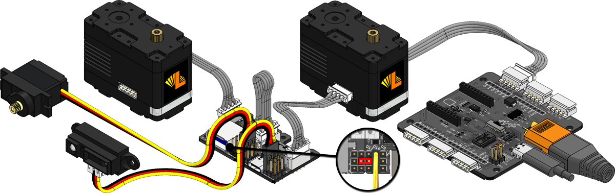
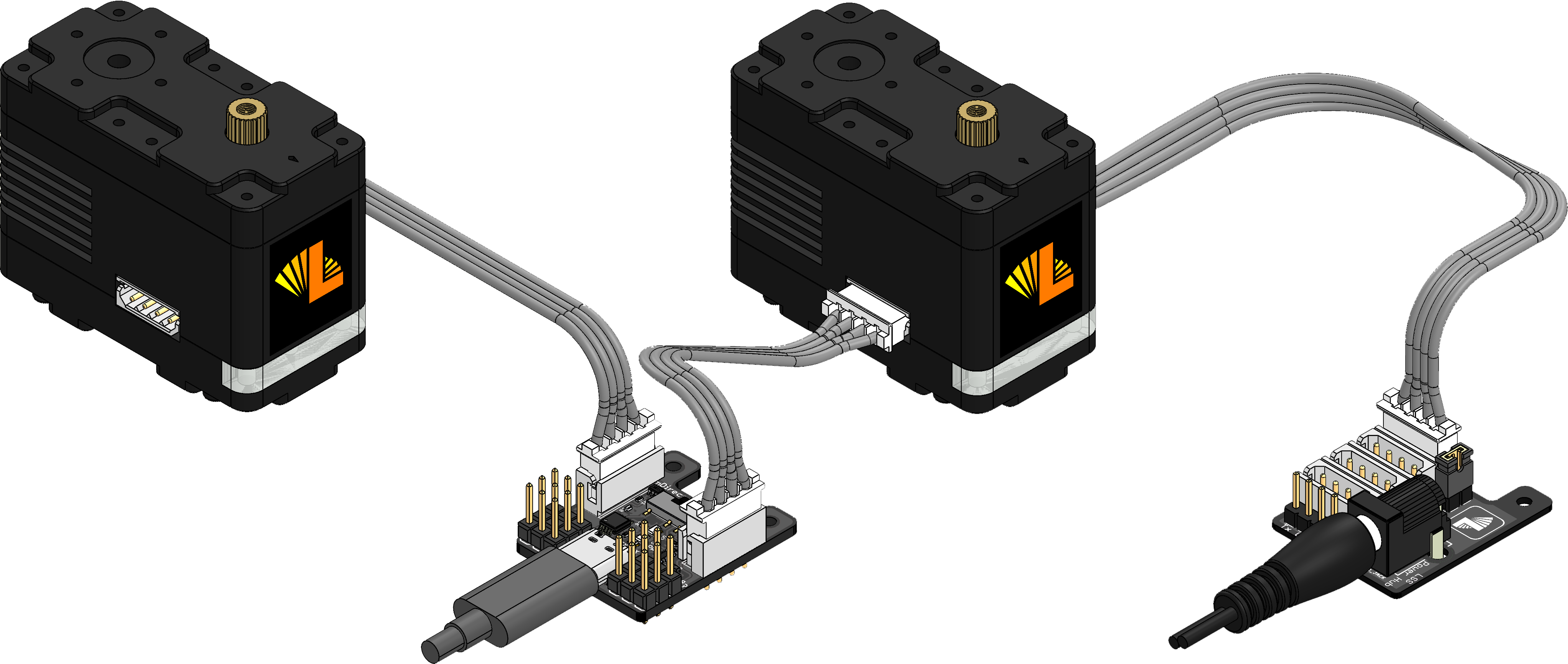
| Sample Wiring / Use |
|
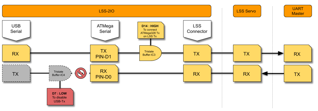
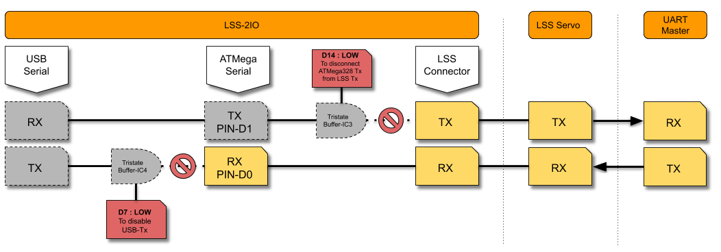
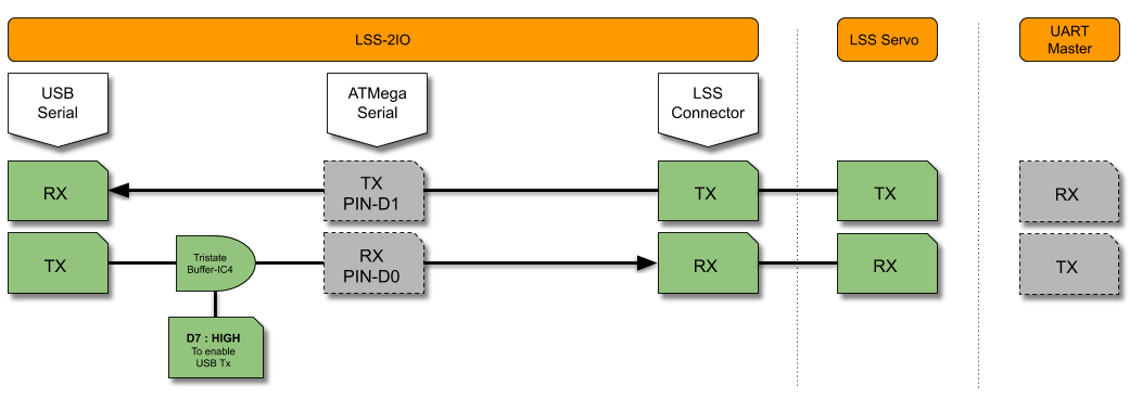
Internal Serial Connection
In this mode, the board is effectively a "peripheral". In order to respond to LSS commands, it needs to be running appropriate code, or the default Lss2IO Arduino sample program. The pinout is as follows:
- ATMega328P's Tx pin (D1) is connected to the LSS Tx line through a tri-state buffer (IC3) that can be enabled or disabled with pin D14.
- ATMega328P's Rx pin (D0) is connected to the LSS Rx line.
Therefore data that is sent from an external UART device will be received on the LSS Rx line and the ATMega328P Rx pin. The LSS 2IO USB-to-Serial IC Tx is connected to the ATMega328P Rx (pin D0) through another tri-state buffer (IC4) that can be enabled/disabled with pin D7. The Lss2IO Arduino code inherently takes care of managing the pins D14 and D7 as follows :
- D7 is LOW: to disconnect LSS 2IO USB-to-Serial IC Tx from ATMega328P Rx (pin D0) allowing the ATMega328P to receive data from the UART controller device as LSS 2IO USB-to-Serial IC Tx is HIGH when LSS 2IO is powered.
- D14 is HIGH: when the 2IO Board is sending data on the LSS Tx line to an external UART device Rx pin. LSS Tx line is asserted to the 2IO Tx pin :
- D14 is LOW: when the 2IO Board is not sending data on the LSS Tx line. The 2IO frees up the LSS Tx line to avoid bus congestion (when 2 devices sends data at the same time) :
Pin / ID Default Assignment
The following pinout is used in the sample code so as to not interfere with any other guides or manuals. This pinout can be changed in the Arduino program.
| PIn/Device | ID | Middle Pin Supply | Notes |
| 2IO Master ID | 207 | - | RGB LED |
| A3 | 203 | 5V | Analog Pin |
| A4 | 204 | 5V | Analog Pin |
| A5 | 205 | 5V | Analog Pin |
| D9 | 209 | Not Connected | Digital Pin |
| D10 | 210 | Not Connected | Digital Pin |
| D11 | 211 | Not Connected | Digital Pin |
| To change the ID,s you can look at the "CID" command HERE | |||
Arduino
| Switch Position | Mode Information |
| In this mode, the 2IO Board acts as a "controller", or an Arduino-based robot controller / "Robot Brain" that can control LSS servos. When in Arduino mode, the 2IO board can be loaded with any Arduino program / sketch via the Arduino IDE. In IDE, select "Tools -> Arduino Nano" and "ATMega328P Processor" should be selected. Making sure that the correct COM port is also selected (which is computer dependent). The Official Lynxmotion Smart Servo (LSS) Arduino Library & Examples could be a good starting point. Use-cases:
|
| Sample Wiring / Use |
|
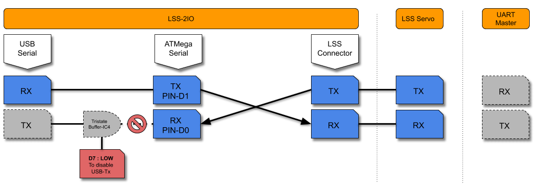
Internal Serial Connections
In this mode, the board is effectively a "peripheral". With the 2IO Board in Arduino mode:
- ATMega328P Tx pin (D1) is connected to the LSS Rx line
- ATMega328P Rx pin (D0) is connected to the LSS Tx line. Therefore, the 2IO can send and receive data to/from LSS servos.
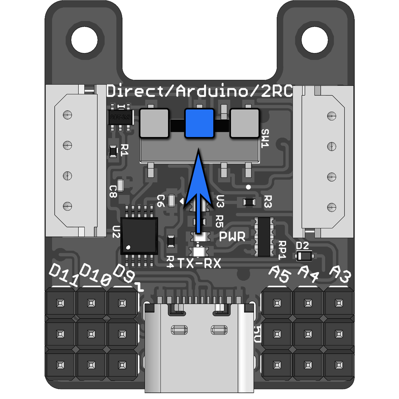
Direct (USB to Serial)
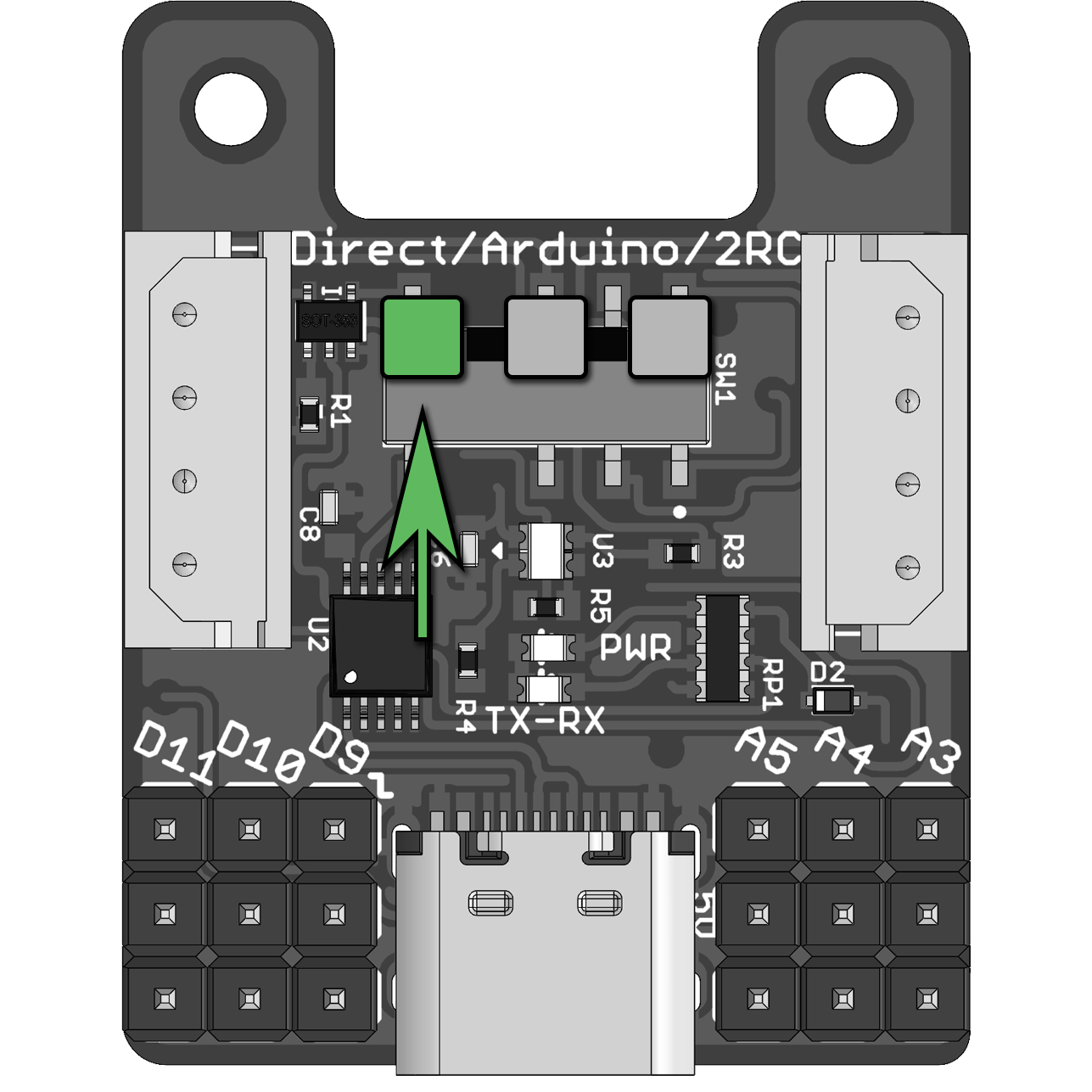
| Switch Position | Mode Information |
| In this mode, the LSS 2IO Board will act as a USB-to-UART converter allowing to control Lynxmotion Smart Servos (LSS) with a USB device (Computer, Raspberry Pi, etc..). To use this mode, the switch should be in the "Direct" position. It is also important to make sure that the ATMega328P is not loaded with a sketch making use of the ATMega328P hardware serial pins (D0 and D1). The best way to make sure of that, would be to load a "BareMnimum" Arduino sketch that can be found in Arduino IDE File -> Examples -> 01.Basics. The pin D7 should also not be set LOW (by default, this pin is HIGH by a pull-up resistor R1). Use-cases :
In order for this to work, it's best to flash the board with a simple sketch that will handle the buffer configuration. |
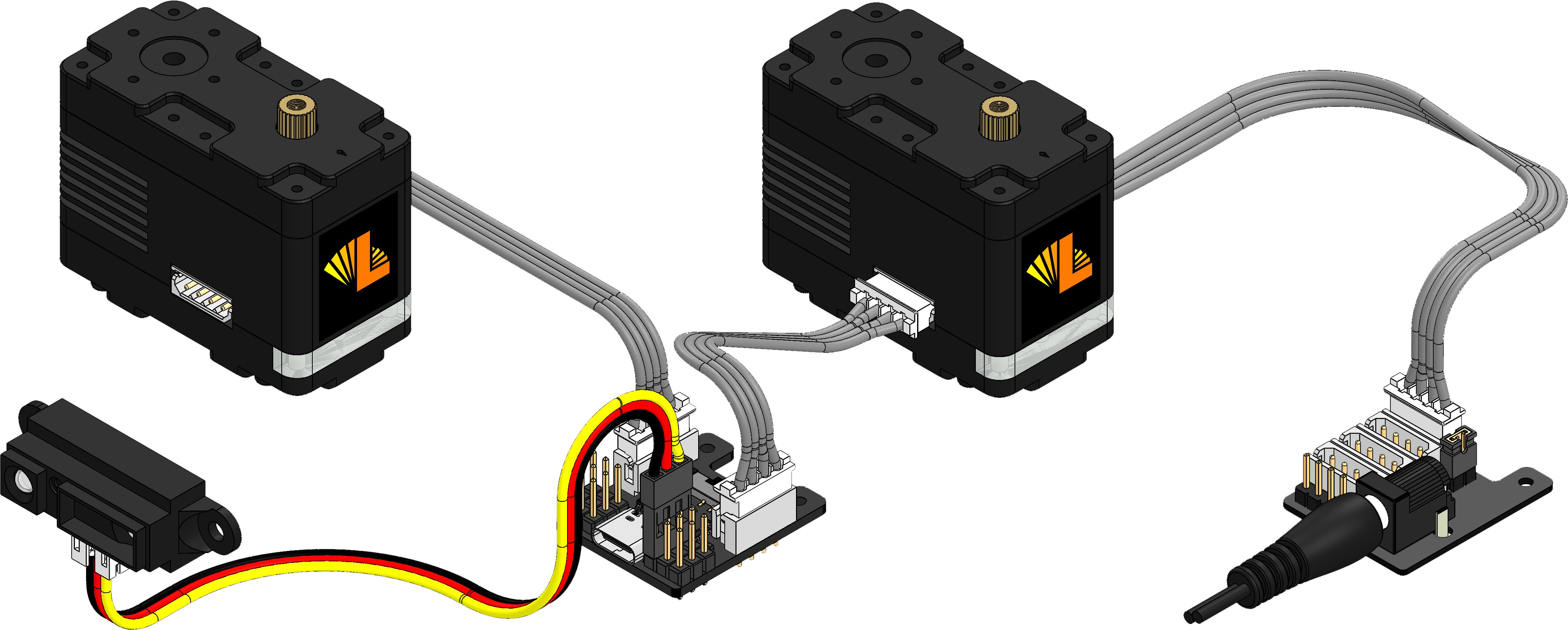
| Sample Wiring / Use |
|
Internal Serial Connections
With the 2IO Board in Direct mode (Switch on "Direct" position), the USB-to-Serial IC Rx is connected to the LSS Tx line and the USB-to-Serial IC Tx is connected to the LSS Rx line. Therefore, the USB Device can send and receive data to/from LSS servos.
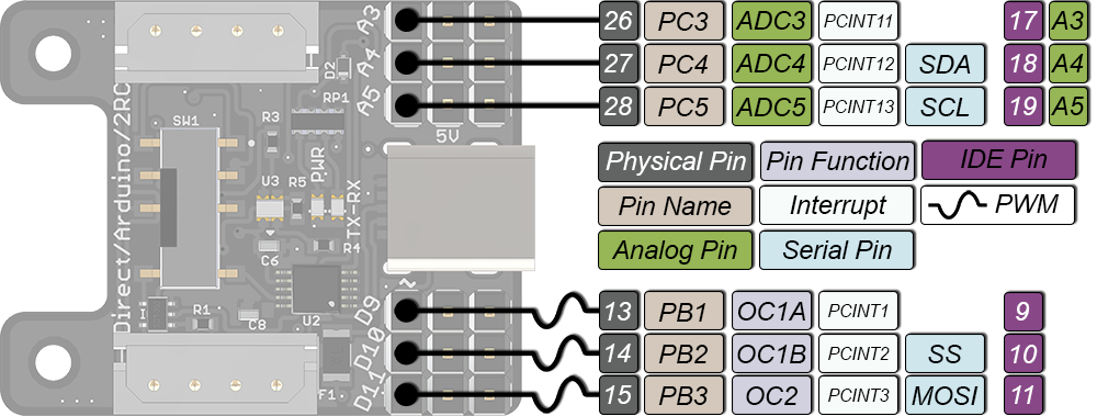
Advanced Pinout
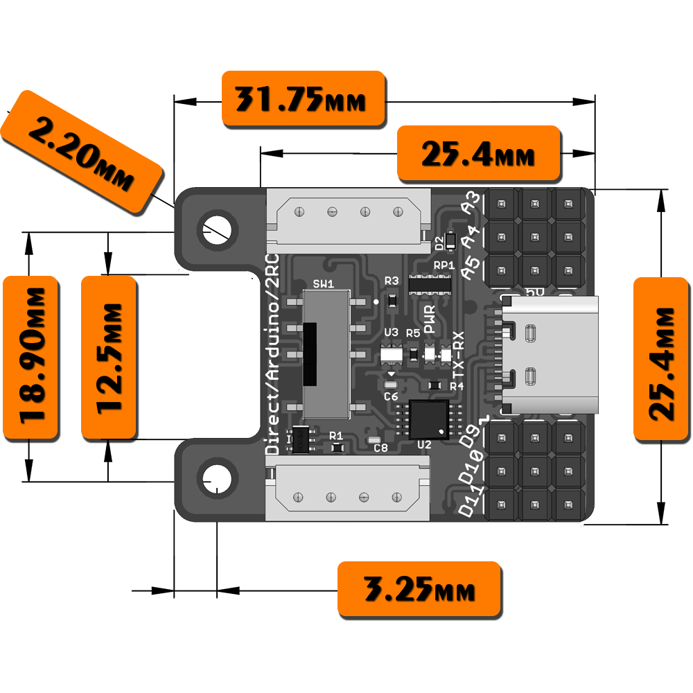
Dimensions & Mounting
|  |