LSS-ADA Board (Type-C)
Table of Contents
Description
The Lynxmotion Smart Servo (LSS) Adapter Board is an electronic board which allows for easy connection to and control of the Lynxmotion Smart Servos. The board includes a variety of features and functions as a central power distribution board via six LSS connectors. The LSS Adapter is ideally intended to be powered from a LiPo battery through the onboard male XT60 connector, or with a wall adapter equipped with a female XT60 connector. There are many ways to interface with this board, as described below.
Features
- Control LSS actuators on the same bus via 6x connectors
- Onboard Bee Socket (XBee, Bluetooth Bee WiFi Bee modules)
- Can function as a USB XBee explorer board
- Arduino shield compatible using stacking headers
- Selectable control method: USB, Arduino or XBee
- Raspberry Pi B+/A+/3 mounting hole compatibility
- XT60 connector for power input
- Automatic logic power selection (USB/External)
Specifications
- Continuous current per connector: 3A (max)
- Built-in USB to serial (V1.0 & 1.1 FTDI / V1.2 CH340)
- Built-in 5V regulator
- Built-in 3.3V regulator
- USB Type-C connector
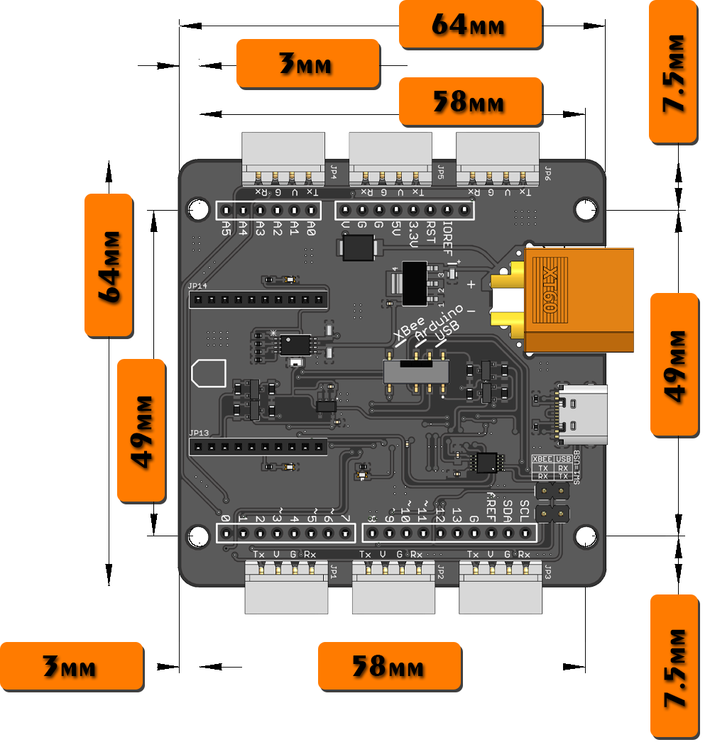
- Dimensions: 64 x 64 x 15mm
- Mounting hole diameter: 3.1mm
Pinout & Wiring
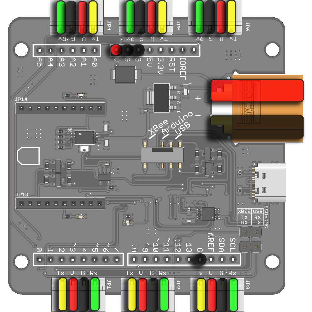
 | Servo Vin: V on the LSS connectors, XT60's Vin and Arduino's Vin (red dot in the picture in left) are connected. Refer to the Voltage section of the LSS - Specifications page for more information on LSS operating voltage. | |
 | Ground (GND): This pin should be connected to both the communication source's ground, as well as that of the power source. G on LSS connectors, XT60's GND/- and Arduino's GND pins are connected. | |
 | LSS Adapter Tx pin: In serial mode, this pin should be connected to the servo's Rx serial pin. If you are using the Lynxmotion serial cables, simply plug in the servo to the LSS adapter. | |
 | LSS Adapter Rx pin: In serial mode, this pin should be connected to the servo's Tx serial pin. If you are using the Lynxmotion serial cables, simply plug in the servo to the LSS adapter. |
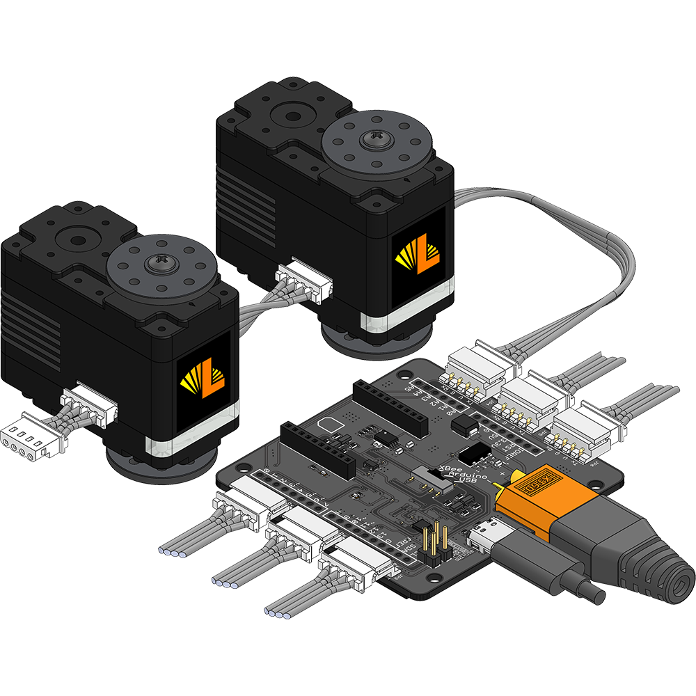
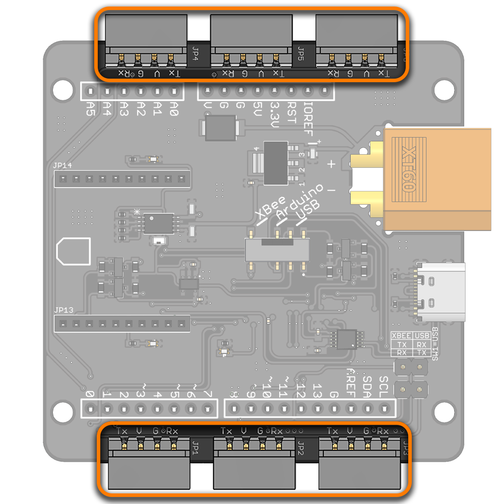
The LSS adapter allows up to six sets of servos to be connected to the same bus and share the same power supply, which greatly simplifies wiring for more complex robots. For example, the servos used in an 18 degree of freedom hexapod robot can be split into groups of three for each leg. |
Power | |
(1) XT60 Connector for 6V-12V main external power input (Refer to the Voltage section of the LSS - Specifications page for more information on LSS operating voltage.). (2) USB 5V power input which powers the Serial chip and the Bee socket (if no 6V-12V external power input is connected). It doesn't power the servos nor the Arduino. (3) USB 5V/On-board regulator 5V auto-switching stage. USB is the primary power source for the 5V bus. This means that if both USB and an external power supply are connected, USB will be automatically chosen to power the 5V bus. (4) Arduino Vin and GND pins. Arduino Vin is connected to the external power supply through a Schottky diode. Serial Chip The serial chip is powered with, either the USB 5V or the onboard 5V regulator through a 6V-12V external power supply via the XT60 connector. If both USB and an external power supply are connected, USB will be automatically chosen to power the serial chip. Arduino In the case where the LSS Adapter is stacked on top of a shield-compatible Arduino microcontroller board, the Arduino can be powered from the Vin pin which is connected to the external power supply through a Schottky diode. If the Arduino Board is powered separately via a different external power supply (ex. connected to the Arduino's barrel connector), it will NOT provide power to the LSS Adapter. The LSS adapter is designed to power the Arduino, but not vice-versa. As such, it is suggested that only ONE 6-12V power source be connected to the LSS Adapter. | |
Servos To power the servos, an external power supply (6V to 12V) is needed (more information in Voltage section of the LSS - Specifications). The external power supply can be a battery or an AC-to-DC wall adapter with a female XT60 connector. The four pins of all six connectors on the board are connected to one another. Each connector (on both the board and on each servo) can handle a maximum of 3A. The LSS Adapter is intended to provide sufficient current to all six connectors. In higher current applications, be sure to select a power supply / source which can provide the necessary current for all servos. Each LSS connector on the LSS Adapter is rated for 3A maximum continuous current. Therefore, the maximum number of servos that can be used on each channel/connector will strongly depend on the application and how much current each servo consumes. For example, if an application requires that servos are consuming 500mA (each), 6 LSS can be used on one connector/channel. Please refer to the LSS - Specifications - Performance Graph to estimate the current consumption based on torque. 5V-PWR LED The 5V-PWR Led will light green if an appropriate 6V-12V external power supply is connected through the XT60 connector and/or a USB 5V is connected through the USB Type-C connector. | |
Communication Modes
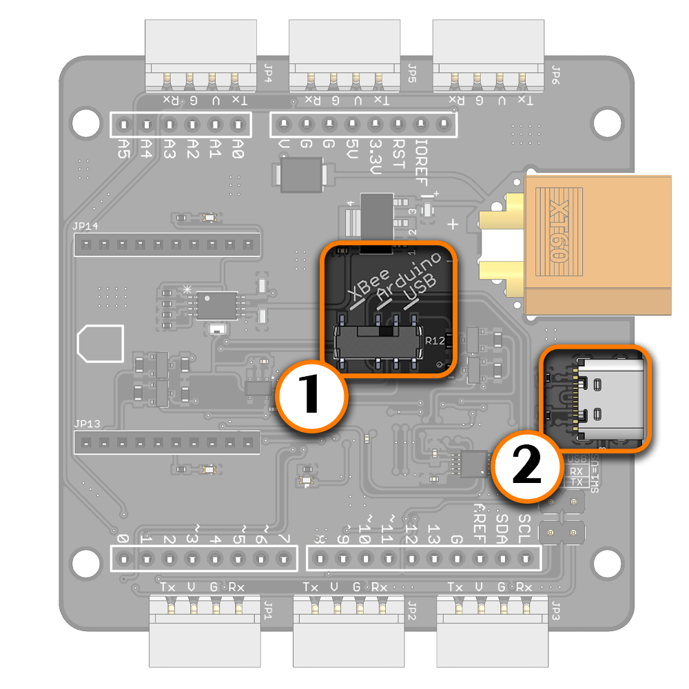
Using the LSS Adapter Board is fairly simple and user-friendly. The configuration switch SW1 on the board allows the user to select one of the following three communication methods. A communication mode is chosen by sliding the switch to the desired position on the board. For example, for USB communication, slide the switch to "USB". The two XBEE to USB jumpers should NOT be in place in any communication mode except for the "USB Explorer" feature (servos won’t be recognized if the jumpers are present). The intended uses include:
- Arduino microcontroller with shield compatibility (ex. Arduino Uno)
- USB Type-C (ex: computer, laptop, Raspberry Pi)
- Wireless module with XBee footprint (Bluetooth Bee, WiFi Bee etc.)
- TTL UART Microcontroller or FPGA control (5V) via Tx, Rx, GND pins of the LSS connectors
Arduino | ||
Hardware Serial To use the LSS Adapter Board with an Arduino microcontroller board, the mode selection switch SW1 should be set to "Arduino". This configuration allows communication with the LSS actuators from an Arduino Board and can be used to build autonomous or semi-autonomous robots. When "Arduino" is selected on the communication switch:
This way, the Arduino communicates with the LSS actuator through the LSS Adapter Board. Note that the Arduino's GND pins are all connected to the LSS Adapter's GND. The XBEE-USB jumpers do NOT need to be in place. If you want to upload new code to the Arduino board while it is connected to the LSS Adapter, set the switch to USB. Software Serial Arduino digital pins 8 and 9 are also connected on the board in order to use software serial. This allows the Arduino to communicate with both the LSS servos which are connected to the LSS adapter, as well as an external module connected to the Bee socket. Should no Bee module be connected, the software serial pins can still be used when the switch is placed in "XBee" mode :
| ||
Stacking The LSS Adapter is Arduino shield compatible, and additional shields can be stacked on top of the adapter. The pin connections are as follows:
The male to female (M/F) stacking headers suggested are 0.1" (2.54mm) pitch, 16mm male (or higher) contact length + female header (1x 6 pin, 2x 8 pin, 1x 10 pin). If no additional shields are stacked on top of the adapter, M/M headers can be used. | ||
USB | ||
(1) Switch to USB (2) USB Type-C connected to a USB device To use the LSS Adapter Board with a standard computer, laptop or Raspberry Pi through USB, the switch SW1 should be set to "USB" mode. This configuration allows communication with the LSS actuators by sending serial commands from a USB host device via the serial chip. When USB is selected on the communication switch, the serial Rx is connected to the LSS actuator's Tx and serial Tx is connected to the LSS actuator's Rx. The XBEE-USB jumpers do NOT need to be in place. As such, the LSS Adapter is also compatible with a Raspberry Pi using the USB connector. The switch needs to be set to USB mode, and the USB Type-C connected to one of the Raspberry Pi's USB ports. Serial USB to Serial Drivers V1.0 & V1.1 uses the FT232RL FTDI chip to convert USB to UART. Most operating systems will automatically detect the FTDI chip and install the correct VCP drivers. In case this is not done automatically, VCP drivers for the FT232RL chip can be downloaded through this link (choose the VCP driver which corresponds to your operating system). V1.2 uses the CH340 chip to convert USB to UART. Most operating systems will automatically detect the CH340 chip and install the correct drivers. In case this is not done automatically, CH340 drivers can be downloaded through this link . USB-Tx LED : This Led blinks to indicate transmission of data from the serial chip. USB-Rx LED : This Led blinks to indicate receiving of data on the serial chip. | ||
Raspberry Pi & Power The LSS Adapter's onboard 5V regulator does not provide enough current to power a Raspberry Pi and as such it is recommended that a Raspberry Pi be powered separately using an appropriate 5V, 2A+ USB wall adapter or 5V voltage adapter (for example a 5V portable phone charger). Mounting The four mounting holes on the LSS adapter line up with the mounting holes of a Raspberry Pi B+/A+/3, though it is important to note that the hole diameter of the mounting holes on a Raspberry Pi are 2.75mm, whereas the mounting hole diameter on the LSS Adapter is 3.10mm. As such, the standard M3 standoffs and screws which are part of the Lynxmotion SES V2 system cannot be used. Standoffs must be sufficiently high in order to clear all pins of the Raspberry Pi. | ||
XBee | ||
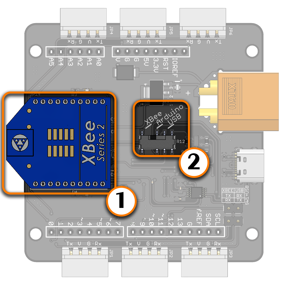
(1) Bee socket compatible wireless module (2) Switch set to XBee mode Bee Wireless Module Although the LSS Adapter has no onboard programmable microcontroller, semi-autonomous / wirelessly controlled robots can be created where an external device like a computer, laptop, tablet or microcontroller sends and receives appropriate commands. The external device needs to be equipped with an appropriate wireless module which is capable of sending/receiving signals wirelessly to the adapter via a Bee compatible wireless module. When connecting the module, ensure the orientation matches that on the screen and that the mode selection switch SW1 should be set to "XBee". The XBEE-USB jumpers do NOT need to be in place. Bee Wireless Module + Arduino Digital pins 8 and 9 of a shield-compatible Arduino are also connected on the board in order to use software serial. This allows an Arduino to communicate with both the LSS servos (which are connected to the LSS adapter) as well as an external module connected to the Bee socket. Should no Bee module be connected, the software serial pins can still be used when the switch is placed in XBee mode.
| ||
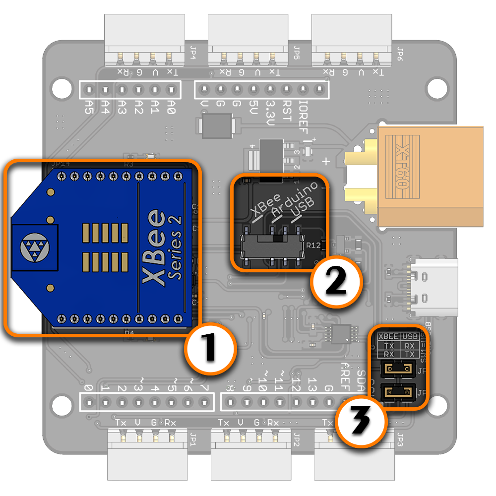
(1) Bee socket compatible wireless module (2) Switch set to USB mode (3) Both XBee to USB jumpers in place XBee Explorer Feature The LSS Adapter Board can be also used as a USB XBee explorer board to communicate with and/or configure an XBee module via the serial chip. The switch should be set to "USB" mode. Note that this is the only mode where the XBEE to USB jumpers should be in place. All LSS servos are on the same bus and will receive the same communications taking place between the USB host and XBee module, therefore it is suggested to unplug all other devices (including servos) in this mode. RSSI LED : this Led lights every time the connected XBee module receives data. Its intensity represents the RSSI value of the last-received data: a brighter light means a higher RSSI value and better signal quality. | ||
Dimensions
The PCB measures 64mm x 64mm square (not including connectors, USB and XT60 which protrude from three sides), and the four 3.10mm diameter mounting holes are located at 49mm x 58mm. The low profile female headers extend 7.4mm below the board, and the tallest component on top of the board protrudes 5.22mm. |


