LSS-LED Board
Last modified by Eric Nantel on 2025/03/19 14:08
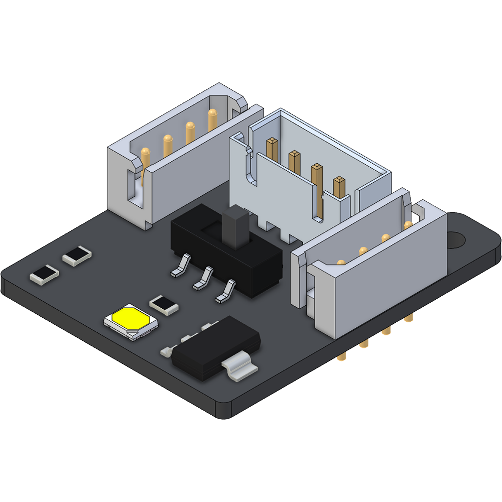

Table of Contents
Description
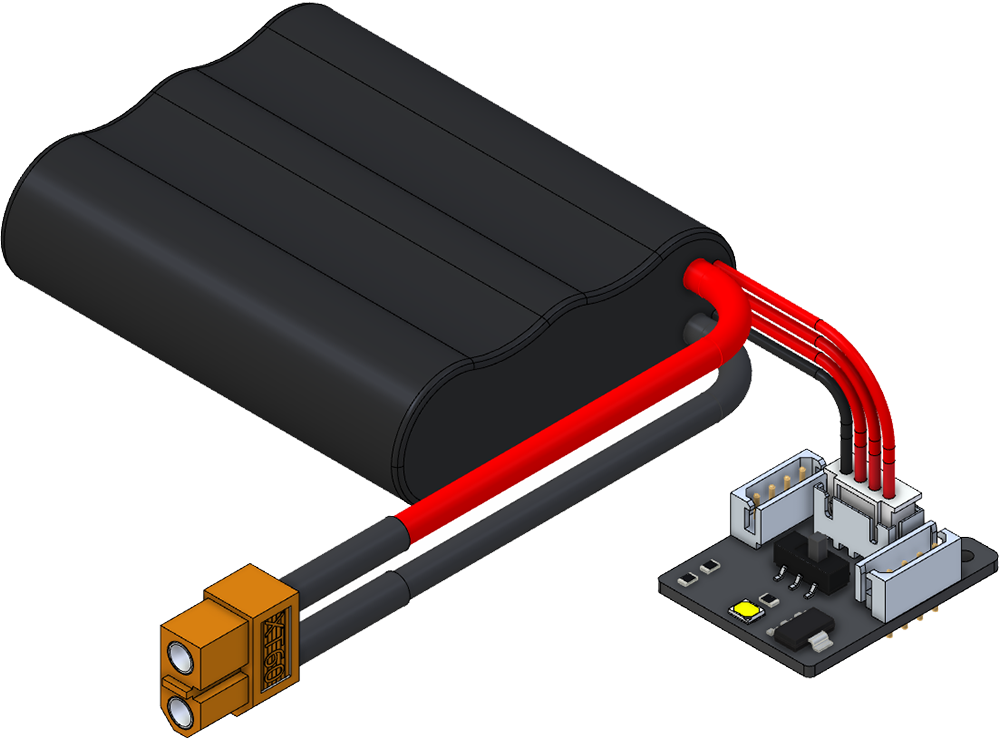
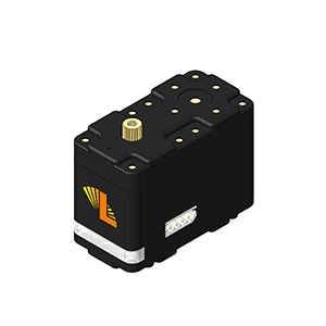
The Lynxmotion (LSS) - LED module is intended to add lighting to your servo erector set (SES) v2 project. The module is meant to be connected to the standard mounting of an Lynxmotion Smart Servo (LSS) Motor and can be added to the serial bus. Like the LSS which can be operated over a range of input voltages, this LED module is meant to operate between 6V and 12V. The module can be powered one of two ways where the onboard switch selects which of the two sources powers the LED:
- Option 1: Four-pin LSS bus (Tx, GND, 12V, Rx)
- Option 2: Four-pin, three cell Lithium balance port (3 individual cells = 11.1V)
Features
- Bright cool white LED
- On / Off switch (act as an isolator for different power input as well)
- 2x LSS connectors to power the LED and transfer to the next unit in the LSS Bus.
- LSS motor mounting
Specifications
- Input Voltage: 12V Nominal (6.4V to 18V)
- Connections:
- LSS Connector (Molex 99990988)
- Lithium balance port (JST B4B-XH-A)
- LED: Everlight 37-21S (~38 lumen white LED)
- Current: ~100 mA
CAD Files
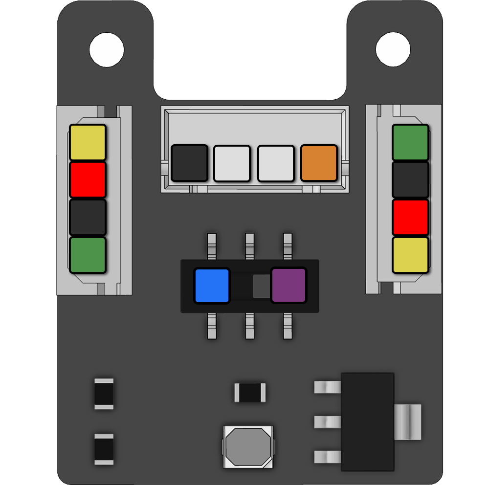
Pinout
|  | Positive LSS: Voltage Input from the LSS connectors |
 | Positive Balance: Voltage Input from the balance port | |
 | Ground (0V): All common grounds | |
 | LSS Connectors: LED will be OFF Balance Port: LED will be ON | |
 | LSS Connectors: LED will be ON Balance Port: LED will be OFF | |
 | Not Connected | |
 | Servo Rx pin (Rx): In serial mode, this pin should be connected to the Tx pin of a TTL serial device. | |
 | Servo Tx pin (Tx): In serial mode, this pin should be connected to the Rx pin of a TTL serial device. |
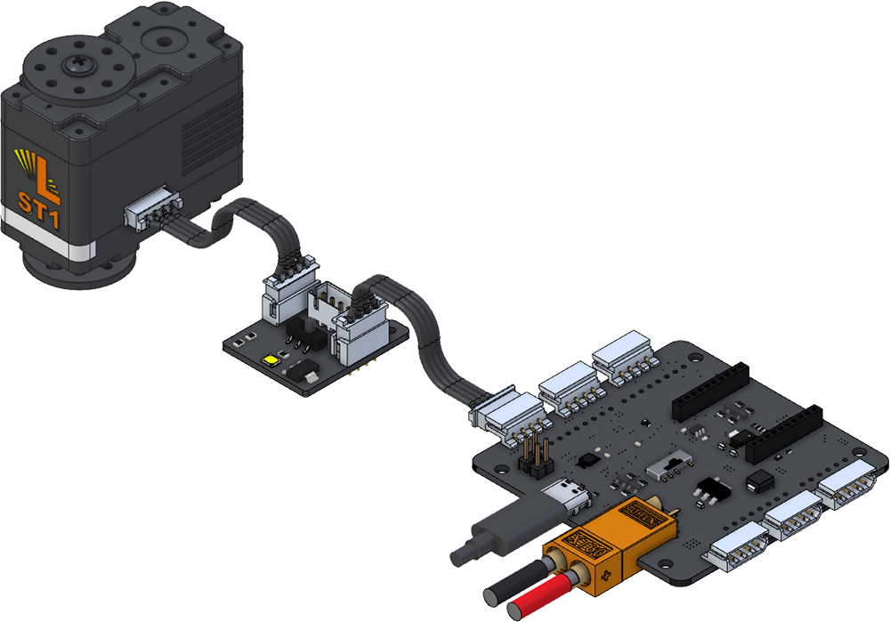
Wiring
| LSS Bus | 12V Battery (balance port) |
|
|
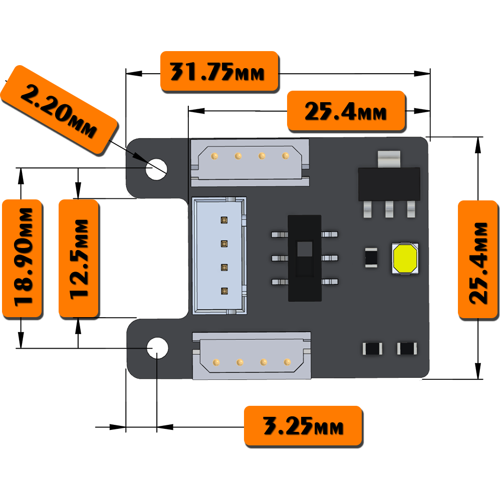
Dimensions & Mounting
|  |