LSS-PRO Communication Protocol
Page Contents
Serial Protocol
The Lynxmotion Smart Servo (LSS) PRO serial protocol was created in order to be as simple and straightforward as possible from a user perspective ("human readable format"), while at the same time staying compact and robust yet highly versatile. The protocol was based on Lynxmotion's Smart Servo (LSS) protocol, which itself was based on the SSC-32 & SSC-32U RC servo controllers. The LSS PRO series and normal LSS share many of the same commands, but because of higher angular precision, slightly different operation and different features, the two protocols do not fully overlap.
In order to be able to control each servo individually with commands, the first step should be to assign a different ID number to each servo (see details on the Configure ID, or "CID" command here). Only the servo(s) which have been configured to a specific ID will act on a command sent to that ID. There is currently no CRC or checksum implemented as part of the protocol.
Action Commands
Action commands tell the servo, within that session, to do something (i.e. "take an action"). The types of action commands which can be sent are described below, and they cannot be combined with other commands such as queries or configurations. Only one action command can be sent at a time. Action commands are session-specific, therefore once a servo is power cycled, it will not have any "memory" of previous actions or virtual positions (described below). Action commands are sent serially to the servo and must be sent in the following format:
- Start with a number sign # (Unicode Character: U+0023)
- Servo ID number as an integer (assigning an ID described below)
- Action command (one or more letters, no whitespace, capital or lowercase from the list below)
- Action value in the correct units with no decimal
- End with a carriage return \r or <cr> Unicode Character (U+000D)
Ex: #5D130000<cr>
This sends a serial command to all servo's RX pins which are connected to the bus and only servo(s) with ID #5 will move to a position (13000 in hundredths of degrees) of 130.00 degrees. Any servo on the bus which does not have ID 5 will take no action when receiving this command.
Modifiers
Modifiers can only be used with certain action commands. The format to include a modifier is:
- Start with a number sign # (Unicode Character: U+0023)
- Servo ID number as an integer
- Action command (one to three letters, no spaces, capital or lowercase from a subset of action commands below)
- Action value in the correct units with no decimal
- Modifier command (one or two letters from the list of modifiers below)
- Modifier value in the correct units with no decimal
- End with a carriage return \r or <cr> Unicode Character (U+000D)
Ex: #5D13000T1500<cr>This results in the servo with ID #5 rotating to a position (1800 in tenths of degrees) of 130.00 degrees in a time ("T") of 1500 milliseconds (1.5 seconds).
Queries
Query commands request information from the servo. Query commands are also similar to action and configuration commands and must use the following format:
- Start with a number sign # (Unicode Character: U+0023)
- Servo ID number as an integer
- Query command (one to four letters, no spaces, capital or lower case)
- End with a carriage return \r or <cr> Unicode Character (U+000D)
Ex: #5QD<cr> Query the position in (hundredths of) degrees for servo with ID #5The query will return a serial string (almost instantaneously) via the servo's Tx in the following format:
- Start with an asterisk * (Unicode Character: U+0023)
- Servo ID number as an integer
- Query command (one to four letters, no spaces, capital letters)
- The reported value in the units described, no decimals.
- End with a carriage return \r or <cr> Unicode Character (U+000D)
There is currently no option to control how fast a servo replies after it has received a query command, therefore when sending a query command to the bus, the controller should be prepared to immediately "listen" for and parse the reply. Sending multiple queries to multiple servos on a bus in fast succession may result in replies overlapping and giving incorrect or corrupt data. As such, the controller should receive a reply before sending a new query command. A reply to the query sent above might be:
Ex: *5QD13000<cr>
This indicates that servo #5 is currently at 130.00 degrees (13000 tenths of degrees).
Configurations
Configuration commands and corresponding values affect a servo's defaults which are written to and read from the servo's EEPROM. These configurations are retained in memory after the servo is reset or power is cut / lost. Some configuration commands affect the session, while others do not. In the Command table below, the column "Session" denotes if the configuration command affects the session. Not all action commands have a corresponding configuration command and vice versa. Configuration commands are not cumulative; this means that if two of the same configuration commands are sent, one after the next, only the last configuration is used and stored.
The format to send a configuration command is identical to that of an action command:
- Start with a number sign # (Unicode Character: U+0023)
- Servo ID number as an integer
- Configuration command (two to four letters, no spaces, capital or lower case)
- Configuration value in the correct units with no decimal
- End with a carriage return \r or <cr> Unicode Character (U+000D)
Ex: #5CO-500<cr>
This configures an absolute origin offset ("CO") with respect to factory origin of servo with ID #5 and changes the offset for that session to -5.00 degrees (500 hundredths of degrees). Once the servo is powered off and on, zeroing the servo will cause it to move to -5.00 degrees with respect to the factory origin and report its position as 0 degrees. Configuration commands can be undone / reset either by sending the servo's default value for that configuration, or by doing a factory reset that clears all configurations (through the button menu or with DEFAULT command described below).
Session vs Configuration Query
By default, the query command returns the session's value. Should no action commands have been sent to change the session value, it will return the value saved in EEPROM which will either be the servo's default, or modified with a configuration command. In order to query the value stored in EEPROM (configuration), add a '1' to the query command:
Ex: #5CSR10<cr> immediately sets the maximum speed for servo #5 to 10rpm (explained below) and changes the value in memory.
After RESET, a command of #5SR4<cr> sets the session's speed to 4rpm, but does not change the configuration value in memory. Therefore:
#5QSR<cr> or #5QSR0<cr> would return *5QSR4<cr> which represents the value for that session, whereas
#5QSR1<cr> would return *5QSR10<cr> which represents the value in EEPROM
The ability to store a "virtual angular position" is a feature which allows for rotation beyond 360 degrees, permitting multiple rotations of the output horn, moving the center position and more. The "absolute position" would be the angle of the output shaft with respect to a 360.00 degree circle and can be obtained by taking the modulus (with respect to 360 degrees) of the value. For example if the virtual position is reported as 153350 (or 1533.50 degrees), taking the modulus would give 93.5 degrees (36000 * 4 + 9350 = 153350) as the absolute position (assuming no origin offset).
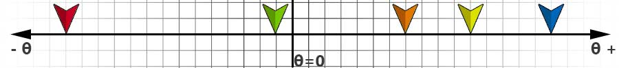
In this example, the gyre direction (explained below, a.k.a. "rotation direction") is positive (clockwise), and origin offset has not been modified. Each square represents 30 degrees. The following command is sent:
#1D-3000<cr> This causes the servo to move to -30.00 degrees (green arrow)
#1D21000<cr> This second position command is sent to the servo, which moves it to 210.00 degrees (orange arrow)
#1D-42000<cr> This next command rotates the servo counterclockwise to a position of -420.00 degrees (red arrow), which means one full rotation of 360 degrees plus 60.00 degrees (420.00 - 360.00), with a virtual position of -420.0 degrees.
Although the final physical position would be the same as if the servo were commanded to move to -60.00 degrees, the servo is in fact at -420.00 degrees.
#1D48000<cr> This new command is sent which would then cause the servo to rotate from -420.00 degrees to 480.00 degrees (blue arrow), which would be a total of 900 degrees of clockwise rotation, or 2.5 complete rotations.
#1D33000<cr> would cause the servo to rotate from 480.0 degrees to 330.00 degrees (yellow arrow).
If the servo loses power or is power cycled, it also loses the virtual position associated with that session. For example, if the virtual position was 480.00 degrees before power is cycled, upon power up the servo's position will be read as +120.00 degrees from zero (assuming center position has not been modified). The virtual position range at power-up is [-180.00°, 180.00°].
Command List
Latest firmware version currently : v0.0.780
| Communication Setup | |||||||
| Description | Action | Query | Config | Default | Unit | Notes | |
| Reset | RESET | Soft reset | |||||
| Default Configuration | DEFAULT | Revert to firmware default values | |||||
| Firmware Update Mode | UPDATE | Update firmware | |||||
| Confirm Changes | CONFIRM | Confirm the action for some commands | |||||
| ID Number | QID | CID | 0 | Reset required after change. ID 254 is a "broadcast" which all servos respond to. | |||
| Enable CAN Terminal | QET | CET | 1 | 0 or 1 | 0: Disable 1: Enable | ||
| USB Connection Status | QUC | 0 or 1 | 0: Not connected 1: Connected | ||||
| Motion | |||||||
| Description | Action | Query | Config | Default | Unit | Notes | |
| Position in Degrees | D | QD | 0.01° | ||||
| Move in Degrees (relative) | MD | 0.01° | |||||
| Wheel mode in Degrees | WD | QWD | 0.01°/s | A.K.A. "Speed mode" or "Continuous rotation" | |||
| Wheel mode in RPM | WR | QWR | RPM | A.K.A. "Speed mode" or "Continuous rotation" | |||
| Query Motion Status | Q | 1 to 8 integer | See command description for details | ||||
| Query Motion Time | QMT | 0.01s | |||||
| Query Current Speed | QCS | 0.01°/s | |||||
| Limp | L | Removes power from stepper coils | |||||
| Halt & Hold | H | Stops (halts) motion and holds last position | |||||
| Motion Setup | |||||||
| Description | Action | Query | Config | Default | Unit | Notes | |
| Origin Offset | O | QO | CO | 0 | 0.01° | ||
| Angular Range | AR | QAR | CAR | 36000 | 0.01° | ||
| Angular Acceleration | AA | QAA | CAA | L1: 10000 | 0.01°/s^2 | ||
| Angular Deceleration | AD | QAD | CAD | L1: 10000 S1: 10000 M1: | 0.01°/s^2 | ||
| Gyre Direction | G | QG | CG | 1 | 1 or -1 | Gyre / rotation direction: 1= CW (clockwise) -1 = CCW (counter-clockwise) | |
| Maximum Speed in Degrees | SD | QSD | CSD | 0.01°/s | SD / CSD overwrites SR / CSR | ||
| Maximum Speed in RPM | SR | QSR | CSR | RPM | SR / CSR overwrites SD / CSD | ||
| Modifiers | |||||||
| Description | Modifier | Query | Config | Default | Unit | Notes | |
| Speed in Degrees | SD | 0.01°/s | For D and MD action commands | ||||
| Timed move | T | ms | Time associated with D, MD commands | ||||
| Telemetry | |||||||
| Description | Action | Query | Config | Default | Unit | Notes | |
| PCB Temperature | QT | 0.1°C | |||||
| Current | QC | mA | Nominal RMS value to stepper motor driver IC. | ||||
| Model String | QMS | Returns the model of servo (ex: LSS-ST1, LSS-HS1, LSS-HT1) | |||||
| Firmware Version | QF | ||||||
| Serial Number | QN | Returns the unique serial number for the servo | |||||
| Temperature Probe | QTP | 0.1°C | Queries temperature probe fixed to the stepper motor | ||||
| Temp of MCU | QTM | 0.1°C | |||||
| Temp of Controller Error | QTCE | Temperature error status of the motor controller (over-temp error) | |||||
| Temp of Controller Warning | QTCW | Temperature error status of the motor controller (pre-warning) | |||||
| Error Flag | QEF | ||||||
| IMU Linear X | QIX | mm/s^2 | |||||
| IMU Linear Y | QIY | mm/s^2 | |||||
| IMU Linear Z | QIZ | mm/s^2 | |||||
| IMU Angular Accel α | QIA | °/s^2 | Query IMU Angular Accel α (Alpha) | ||||
| IMU Angular Accel β | QIB | °/s^2 | Query IMU Angular Accel β (Beta) | ||||
| IMU Angular Accel γ | QIG | °/s^2 | Query IMU Angular Accel γ (Gamma) | ||||
| RGB LED | |||||||
| Description | Action | Query | Config | Default | Unit | Notes | |
| LED Color | LED | QLED | CLED | 3 | 0 to 7 integer | 0=Off; 1=Red; 2=Green; 3=Blue; 4=Yellow; 5=Cyan; 6=Magenta; 7=White | |
| LED Blinking | QLB | CLB | 0 | ||||
| LED Indicator | QLI | ||||||
Details
Communication Setup
Reset | |
Reset (RESET) Ex: #5RESET<cr> This command does a "soft reset" and reverts all commands to those stored in EEPROM (i.e. configuration commands). Note: after a RESET command is received, the LSS will restart and perform initilization again, making it unavailable on the bus for a bit. See Session, note #2 for more details. | |
Default | |
Default (DEFAULT) Ex: #5DEFAULT<cr> This command sets in motion the reset of all values to the default values included with the version of the firmware installed on that servo. The servo then waits for the CONFIRM command. Any other command received will cause the servo to exit the DEFAULT function. EX: #5DEFAULT<cr> followed by #5CONFIRM<cr> Since it it not common to have to restore all configurations, a confirmation command is needed after a firmware command is sent. Should any command other than CONFIRM be received by the servo after the firmware command has been received, it will exit the command. Note: After the CONFIRM command is sent, the servo will automatically perform a RESET. | |
Update | |
Update (UPDATE) Ex: #5UPDATE<cr> This command sets in motion the equivalent of a long button press when the servo is not powered in order to enter firmware update mode. This is useful should the button be broken or inaccessible. The servo then waits for the CONFIRM command. Any other command received will cause the servo to exit the UPDATE function. EX: #5UPDATE<cr> followed by #5CONFIRM<cr> Since it it not common to have to update firmware, a confirmation command is needed after an UPDATE command is sent. Should any command other than CONFIRM be received by the servo after the firmware command has been received, it will leave the firmware action. Note: After the CONFIRM command is sent, the servo will automatically perform a RESET. | |
Confirm | |
Confirm (CONFIRM) Ex: #5CONFIRM<cr> This command is used to confirm changes after a Default or Update command. | |
ID Number | |
This assigns ID #5 to the servo previously assigned to ID 0 Configure ID Number (CID) Ex: #0CID5<cr> The default ID is 0, so this sets the servo to ID 5. Query ID Number (QID) Ex: #254QID<cr> might return *254QID5<cr> In this case, the broadcast ID is used to ensure the servo connected will reply with the ID. This can be used in case the ID assigned to a servo is forgotten. | |
Enable CAN Terminal Resistor | |
Query Enable CAN Terminal Resistor (QET) Ex: #5QET<cr> might return *QET0<cr> This means that servo with ID 5 is NOT configured as the last servo in the CAN bus. Configure Enable CAN Terminal Resistor (CET) Ex: #5CET1<cr> This commands sets servo with ID 5 as being the last in the CAN Bus. The last servo in a CAN bus must be configured this way. | |
USB Connection Status | |
Query USB Connection Status (QUC) Ex: #5QUC<cr> might return *5QUC1<cr> meaning the servo is connected via USB | |
Motion
Position in Degrees | |
Position in Degrees (D) Example: #5D1456<cr> This moves the servo to an angle of 145.6 degrees, where the center (0) position is centered. Negative values (ex. -176 representing -17.6 degrees) could also be used. A full circle would be from -1800 to 1800 degrees. A value of 2700 would be the same angle (absolute position) as -900, except the servo would move in a different direction. Larger values are permitted and allow for multi-turn functionality using the concept of virtual position (explained above). Query Position in Degrees (QD) Example: #5QD<cr> might return *5QD132<cr> This means the servo is located at 13.2 degrees. Query Target Position in Degrees (QDT) Ex: #5QDT<cr> might return *5QDT6783<cr> The query target position command returns the target virtual position during and after an action which results in a rotation of the servo horn. In the example above, the servo is rotating to a virtual position of 678.3 degrees. Should the servo not have a target position or be in wheel mode, it will respond with the last target position used. | |
Relative Move in Degrees | |
Move in Degrees (MD) Example: #5M1500<cr> The relative move in PWM command causes the servo to read its current position and move by the specified number of PWM signal. For example if the servo is set to rotate CW (default) and an M command of 1500 is sent to the servo, it will cause the servo to rotate clockwise by 90 degrees. Negative PWM value would cause the servo to rotate in the opposite configured direction. | |
Wheel Mode in Degrees | |
Wheel mode in Degrees (WD) Ex: #5WD90<cr> ⚠️ Note: The servo’s Angular Range (AR) must be disabled when using Wheel Mode. This command sets the servo to wheel mode where it will rotate in the desired direction at the selected speed. The example above would have the servo rotate at 90.0 degrees per second clockwise (assuming factory default configurations). Query Wheel Mode in Degrees (QWD) Ex: #5QWD<cr> might return *5QWD90<cr> The servo replies with the angular speed in degrees per second. A negative sign would indicate the opposite direction (for factory default a negative value would be counter clockwise). | |
Wheel Mode in RPM | |
Wheel moed in RPM (WR) Ex: #5WR40<cr> ⚠️ Note: The servo’s Angular Range (AR) must be disabled when using Wheel Mode. This command sets the servo to wheel mode where it will rotate in the desired direction at the selected rpm. Wheel mode (a.k.a. "continuous rotation") has the servo operate like a geared DC motor. The servo's maximum rpm cannot be set higher than its physical limit at a given voltage. The example above would have the servo rotate at 40 rpm clockwise (assuming factory default configurations). Query Wheel Mode in RPM (QWR) Ex: #5QWR<cr> might return *5QWR40<cr> The servo replies with the angular speed in rpm. A negative sign would indicate the opposite direction (for factory default a negative value would be counter clockwise). | |
Status | |||||||||||||||||||||||||||||||||||||||||||||||||||||
Query Status (Q) The status query describes what the servo is currently doing. The query returns an integer which must be looked up in the table below. Ex: #5Q<cr> might return *5Q6<cr>, which indicates the motor is holding a position.
*Value returned (Q)StatusDetailed description If a safety limit has been reached and exceeded, the LED will flash red and the servo will stop providing torque (no longer react to commands which cause the motor to rotate). In order to determine which limit has been reached, send a Q1 command. The servo must be RESET in order to return to normal operation, though if a limit is still detected (for example the servo is still too hot), it will revert back to Safe Mode.
| |||||||||||||||||||||||||||||||||||||||||||||||||||||
Motion Time | |
Query Motion Time (QMT) Ex: #5QMT9000<cr> might return *5QMT1000<cr>, which indicates the motor would take 1.000s to do that movement. This is really important for movement using the modifier "T" as asking a movement that could not be achieved in the time asked will result in no movement. | |
Current Speed | |
Query Current Speed (QCS) Ex: #5QCS<cr> might return *5QCS1245<cr>, which indicate the actuator is moving currently at 12deg/s. | |
Limp | |
Example: #5L<cr> This action causes the servo to go "limp". The microcontroller will still be powered, but the motor will not. As an emergency safety feature, should the robot not be doing what it is supposed to or risks damage, use the broadcast ID to set all servos limp #254L<cr>. | |
Halt & Hold | |
Example: #5H<cr> This command causes the servo to stop immediately and hold that angular position. It overrides whatever the servo might be doing at the time the command is received (accelerating, travelling, deccelerating, etc.) | |
Motion Setup
Origin Offset | |
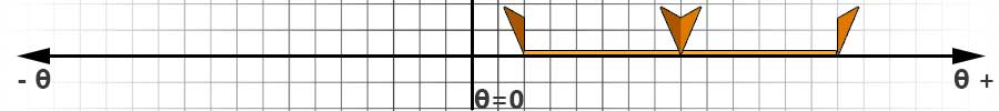
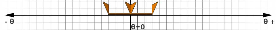
Example: #5O2400<cr>This command allows you to change the origin of the servo in relation to the factory zero position for that session. As with all action commands, the setting will be lost upon servo reset / power cycle. Origin offset commands are not cumulative and always relate to factory zero. In the first image, the origin at factory offset '0' (centered).
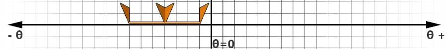
In the second image, the origin, and the corresponding angular range (explained below) have been shifted by +240.0 degrees:
Origin Offset Query (QO) Example: #5QO<cr> might return *5QO-13 This allows you to query the angle (in tenths of degrees) of the origin in relation to the factory zero position. In this example, the new origin is at -1.3 degrees from the factory zero. Configure Origin Offset (CO) Example: #5CO-24<cr> This command allows you to change the origin of the servo in relation to the factory zero position in EEPROM. The setting will be saved upon servo reset / power cycle. Origin offset configuration commands are not cumulative and always relate to factory zero. The new origin is also used in RC mode. In the example, the new origin will be at -2.4 degrees from the factory zero. | |
Angular Range | |
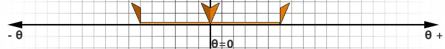
Example: #5AR1800<cr> This command allows you to temporarily change the total angular range of the servo in tenths of degrees. This applies to the Position in Pulse (P) command and RC mode. The default for (P) and RC mode is 1800 (180.0 degrees total, or ±90.0 degrees). The image below shows a standard -180.0 to +180.0 range, with no offset:
Below, the angular range is restricted to 180.0 degrees, or -90.0 to +90.0. The center has remained unchanged.
Finally, the angular range action command (ex. #5AR1800<cr>) and origin offset action command (ex. #5O-1200<cr>) are used to move both the center and limit the angular range:
Query Angular Range (QAR) Example: #5QAR<cr> might return *5AR1800, indicating the total angular range is 180.0 degrees. Configure Angular Range (CAR) This command allows you to change the total angular range of the servo in tenths of degrees in EEPROM. The setting will be saved upon servo reset / power cycle. ⚠️ Note: Setting AR0 removes angular limits and allows continuous rotation. | |
Angular Acceleration | |
The default value for angular acceleration is 100. Accepts values of between 1 and 100. Increments of 10 degrees per second squared. Ex: #5AA30<cr> This sets the angular acceleration for servo #5 to 30 degrees per second squared (°/s2). Query Angular Acceleration (QAA) Ex: #5QAA<cr> might return *5QAA30<cr> This returns the servo's angular acceleration in degrees per second squared (°/s2). Configure Angular Acceleration (CAA) Ex: #5CAA30<cr> This writes the angular acceleration of servo #5 to 30 degrees per second squared (°/s2) to EEPROM. | |
Angular Deceleration | |
The default value for angular deceleration is 100. Accepts values of between 1 and 100. Increments of 10 degrees per second squared. Ex: #5AD30<cr> This sets the angular deceleration for servo #5 to 30 degrees per second squared (°/s2). Query Angular Deceleration (QAD) Ex: #5QAD<cr> might return *5QAD30<cr> This returns the servo's angular deceleration in degrees per second squared (°/s2). Configure Angular Deceleration (CAD) Ex: #5CAD30<cr> This writes the angular deceleration of servo #5 to 30 degrees per second squared (°/s2) to EEPROM. | |
Gyre Direction | |
"Gyre" is defined as a circular course or motion. The effect of changing the gyre direction is as if you were to use a mirror image of a circle. By default: CW = 1; CCW = -1. Ex: #5G-1<cr> This command will cause servo #5's positions to be inverted, effectively causing the servo to rotate in the opposite direction given the same command. For example in a 2WD robot, servos are often physically installed back to back, therefore setting one of the servos to a negative gyration, the same wheel command (ex WR30) to both servos will cause the robot to move forward or backward rather than rotate. Query Gyre Direction (QG) Ex: #5QG<cr> might return *5QG-1<cr> The value returned above means the servo is in a counter-clockwise gyration. Sending a #5WR30 command will rotate the servo in a counter-clockwise gyration at 30 RPM. Configure Gyre (CG) Ex: #5CG-1<cr> This changes the gyre direction as described above and also writes to EEPROM. | |
Maximum Speed in Degrees | |||||||||||
Maximum Speed in Degrees (SD) Ex: #5SD1800<cr> This command sets the servo's maximum speed for motion commands in tenths of degrees per second for that session. In the example above, the servo's maximum speed for that session would be set to 180.0 degrees per second. The servo's maximum speed cannot be set higher than its physical limit at a given voltage. The SD action command overrides CSD (described below) for that session. Upon reset or power cycle, the servo reverts to the value associated with CSD as described below. Note that SD and SR (described below) are effectively the same, but allow the user to specify the speed in either unit. The last command (either SR or SD) received is what the servo uses for that session. Query Speed in Degrees (QSD) Ex: #5QSD<cr> might return *5QSD1800<cr> By default QSD will return the current session value, which is set to the value of CSD as reset/power cycle and changed whenever an SD/SR command is processed. If #5QSD1<cr> is sent, the configured maximum speed (CSD value) will be returned instead. You can also query the current speed using "2" and the current target travel speed using "3". See the table below for an example:
Configure Speed in Degrees (CSD) Ex: #5CSD1800<cr> Using the CSD command sets the servo's maximum speed which is saved in EEPROM. In the example above, the servo's maximum speed will be set to 180.0 degrees per second. When the servo is powered on (or after a reset), the CSD value is used. Note that CSD and CSR (described below) are effectively the same, but allow the user to specify the speed in either unit. The last command (either CSR or CSD) is what the servo uses for that session. | |||||||||||
Maximum Speed in RPM | |||||||||||
Maximum Speed in RPM (SR) Ex: #5SR45<cr> This command sets the servo's maximum speed for motion commands in rpm for that session. In the example above, the servo's maximum speed for that session would be set to 45rpm. The servo's maximum speed cannot be set higher than its physical limit at a given voltage. SR overrides CSR (described below) for that session. Upon reset or power cycle, the servo reverts to the value associated with CSR as described below. Note that SD (described above) and SR are effectively the same, but allow the user to specify the speed in either unit. The last command (either SR or SD) received is what the servo uses for that session. Query Speed in RPM (QSR) Ex: #5QSR<cr> might return *5QSR45<cr> By default QSR will return the current session value, which is set to the value of CSR as reset/power cycle and changed whenever an SD/SR command is processed. If #5QSR1<cr> is sent, the configured maximum speed (CSR value) will be returned instead. You can also query the current speed using "2" and the current target travel speed using "3". See the table below for an example:
Configure Speed in RPM (CSR) Ex: #5CSR45<cr> Using the CSR command sets the servo's maximum speed which is saved in EEPROM. In the example above, the servo's maximum speed will be set to 45rpm. When the servo is powered on (or after a reset), the CSR value is used. Note that CSD and CSR are effectively the same, but allow the user to specify the speed in either unit. The last command (either CSR or CSD) received is what the servo uses for that session. | |||||||||||
Modifiers
Speed | |
Speed in Degrees (SD) Example: #5D0SD180<cr> Modifier (SD) is only for a position (D) or relative position (MD) action and determines the speed of the move in tenths of degrees per second. A speed modifier (SD) of 180 would cause the servo to rotate from its current position to the desired absolute or relative position at a speed of 18 degrees per second. Query Speed (QS) Example: #5QS<cr> might return *5QS300<cr> This command queries the current speed in microseconds per second. | |
Timed move | |
Timed Move (T) Example: #5D15000T2500<cr> Timed move can be used only as a modifier for a position (D, MD) actions. The units are in milliseconds, so a timed move of 2500 milliseconds would cause the servo to rotate from its current position to the desired position in 2.5 seconds. The onboard controller will attempt to ensure that the move is performed entirely at the desired velocity, though differences in torque may cause it to not be exact. This command is in place to ensure backwards compatibility with the SSC-32 / 32U protocol. Note: If the calculated speed at which a servo must rotate for a timed move is greater than its maximum speed (which depends on voltage and load), then it will move at its maximum speed, and the time of the move may be longer than requested | |
Telemetry
Temperature PCB | |
Query Temp PCB (QT) Ex: #5QT<cr> might return *5QT564<cr> The units are in tenths of degrees Celcius, so in the example above, the servo's internal temperature is 56.4 degrees C. To convert from degrees Celcius to degrees Farenheit, multiply by 1.8 and add 32. Therefore 56.4C = 133.52F. | |
Current | |
Query Current (QC) Ex: #5QC<cr> might return *5QC140<cr> The units are in milliamps, so in the example above, the servo is consuming 140mA, or 0.14A. It represents the RMS value. The query calculates the RMS value of the current sent from the motor driver to the stepper motor. | |
Model String | |
Query Model String (QMS) Ex: #5QMS<cr> might return *5QMSLSS-HS1<cr> This reply means that the servo model is LSS-HS1: a high speed servo, first revision. | |
Firmware | |
Query Firmware (QF) Ex: #5QF<cr> might return *5QF368<cr> The number in the reply represents the firmware version, in this example being 368.The command #5QF3<cr> can also be sent and the servo will reply with a 3 numbers firmware version, for example, 368.29.14 | |
Serial Number | |
Query Serial Number (QN) Ex: #5QN<cr> might return *5QN12345678<cr> The number in the response (12345678) would be the servo's serial number which is set and should not be changed by the user. | |
Temperature Probe | |
Query Temp motor Probe (QTP) Ex: #5QTP<cr> might return *5QTP564<cr> The units are in tenths of degrees Celcius, so in the example above, the servo's motor temperature is 56.4 degrees C. To convert from degrees Celcius to degrees Farenheit, multiply by 1.8 and add 32. Therefore 56.4C = 133.52F. | |
Temperature MCU | |
Query Temp MCU (QTM) Ex: #5QTM<cr> might return *5QTM564<cr> The units are in tenths of degrees Celcius, so in the example above, the servo's microcontroller temperature is 56.4 degrees C. To convert from degrees Celcius to degrees Farenheit, multiply by 1.8 and add 32. Therefore 56.4C = 133.52F. | |
Temp Controller Error | |
Query Temp Controller Error (QTCE) Returns the value of the "ot" bit of the motor driver's DRV_STATUS register (addr: 0x6F). If the response is 1, the motor driver has detected overtemperature (over 150℃). | |
Temp Controller Warning | |
Query Temp Controller Warning (QTCW) Returns the value of the "otpw" bit of the motor driver's DRV_STATUS register (addr: 0x6F). If the response is 1, the motor driver has detected overtemperature pre-warning (over 120℃). | |
Error Flag | |||||||||||||||||||||||||||||||||||||||||||||||||||||||||
Query Error Flag (QEF) Ex: #5QEF<cr> might return *5QEF64<cr>
| |||||||||||||||||||||||||||||||||||||||||||||||||||||||||
IMU Linear | |
Query IMU Linear (QIX QIY QIZ) Ex: #6QIX<cr> might return *6QIX30<cr> This command queries servo 6's IMU's linear accelerometer in the X direction. The response is 30mm per second squared. | |
IMU Angular | |
Query IMU Angular (QIA QIB QIG) Ex: #6QIB<cr> might return *6QIB44<cr> This command queries servo 6's IMU's linear accelerometer in the X direction. The response is 4.4 degrees per second squared. | |
RGB LED
LED Color | |||||||||||||||||||
The user defined LED color can be changed permanently (CLED) or until reboot (LED). Ex: #5LED5<cr>, will set the user LED color to Cyan until reboot of the actuator. Ex: #5CLED3<cr>, will set the user LED color to Blue and will be that way ever after rebooting the actuator.
| |||||||||||||||||||


LED Blinking | |||||||||||||||||||
This command allows you to control when the RGB LED will blink the user set color (see RGB LED command for details). This is very useful when visually seeing what the servo is doing. You can turn on or off blinking for various LSS status. The command requires that the servo be RESET. Here is the list and their associated value:
To set blinking, use CLB with the value of your choosing. To activate blinking in multiple status, simply add together the values of the corresponding status. See examples below:Ex: #5CLB0 to turn off all blinking (LED always solid)Ex: #5CLB1 only blink when limp (1)Ex: #5CLB2 only blink when holding (2)Ex: #5CLB12 only blink when accel or decel (accel 4 + decel 8 = 12)Ex: #5CLB48 only blink when free or travel (free 16 + travel 32 = 48)Ex: #5CLB63 blink in all status (1 + 2 + 4 + 8 + 16 + 32)RESETTING the servo is needed. | |||||||||||||||||||
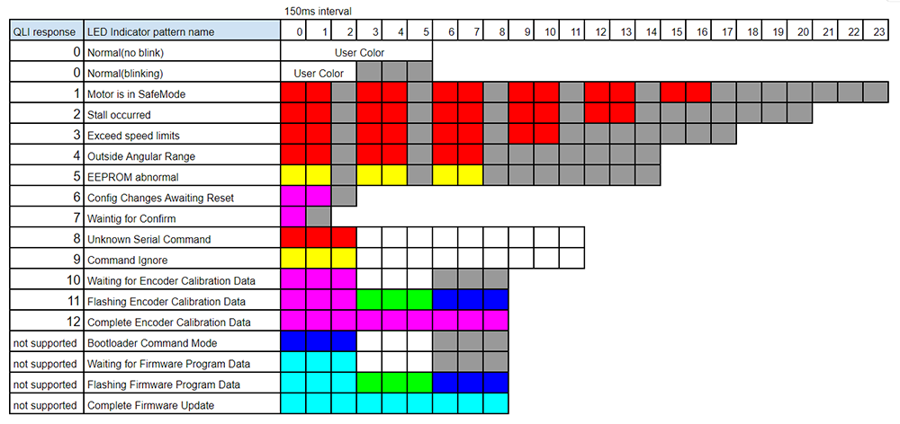
LED Indicator | |
The LED Indicator will reflect the blinking pattern from the LED at a given time. Ex: #5QLI<cr> might return *5QLI4<cr>, and the actuator would be blinking 3 times as an Exceed speed limits error.
| |