
LSS FlowArm

Page Contents
Description
{Coming soon}
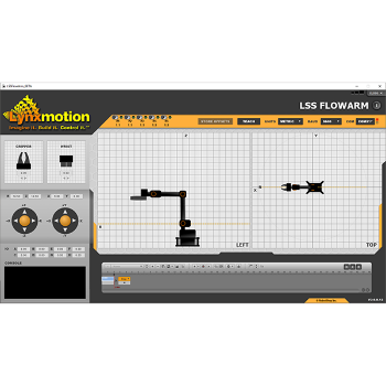
The LSS FlowArm application was created using FlowBotics Studio software and is intended to allow easy control of the standard configuration Lynxmotion Servo Erector Set (S.E.S.) v2 articulated robotic arm. The graphical interface shows a side and top view of the arm, as well as the gripper and wrist. The full-featured built-in sequencer allows you create sequences which have the arm move automatically from one position ("frame") to the next.
Features
- Graphical interface for the Lynxmotion SES V2 articulated robot arm
- Full featured sequencer allows recording and playback of many sequences via keyboard input
- Teach mode allows the user to move the arm and have the virtual arm follow
- Position the arm using rectangular or cylindrical coordinates, virtual joysticks or mouse drag
- Application can be modified via FlowBotics Studio
Initial Setup
In order to understand the features, functionality and nuances of the Lynxmotion smart servos, it is suggested to read through the lynxmotion-smart-servo section of the wiki.
Before assembling the arm, each of the IDs assigned to the servos must correspond with what is needed in the software.
- Base: 1
- Shoulder: 2
- Elbow: 3
- Wrist: 4
- Gripper: 5
To do so, the LSS Configuration Software is used. Follow the procedure outlined here: lss-config-configure-ids
Important note: The software does not take into consideration if a servo has been improperly assembled. If you see that your arm moves differently than the arm on screen, be sure to check the following:
- Servo ID is correctly assigned to each servo and there are no duplicate IDs
- Servos have been assembled in correct orientation (as per assembly manual)
- Servo offsets have been updated if necessary (see procedure below).
Interface
Header

STORE OFFSETS
During the assembly process, if the servo's driving output horn was not rotated (they are shipped with the servo driving horn centered at 0 degrees), and was connected to the brackets at the correct angle (parallel or perpendicular depending on the servo being assembled), there should not be any significant servo offset needed and the arm should match what is displayed on screen. However, should the driving horn have rotated and/or the brackets were not connected at optimal angles, the "STORE OFFSETS" button configures the all of the servo offsets (this makes use of the CO command as part of the LSS Communication Protocol). Before pressing the button, be sure to orient the arm as follows (with the base a, and THEN click the STORE OFFSETS button.
LIMP
Causes all servos to go LIMP (i.e. lose torque). The arm will collapse.
STOP
Causes all servos to stop their motion and hold their position.
TEACH
Teach mode allows a user to physically move the arm to a designed location
In order to ensure the arm does not collapse, pressing the TEACH button will start a 5 second countdown during which the arm will slowly lose torque (angular force) until all servos are limp.
When in teach mode, an orange outline appears over all on-screen fields which would cause a conflict and therefore cannot be used.
CAREFUL: Do not move the servos too quickly. We suggest moving the gripper servo, or temporarily removing the aesthetic shell.
Once the arm is limp, it can be moved physically, and the application will regularly read the physical position of each of the servos and move the virtual arm on screen to match.
Use the sequencer to save each position (frame). Intermediate frames can be added as needed. For more information on the sequencer, refer to the sequencer section below.
GRID / Units
Units can be toggled between Metric or Imperial
BAUD
The baud rate suggested is 115200, which is the default baud rate of the servos. Should a user have changed the baud rate on the servos, it can be selcted using the drop down. Note that the baud rate must be configured to the same value for all servos in order to work.
COM
This field selects which of your computer's COM ports is connected to the LSS Adapter, which is provided with the standard SES v2 articulated robot arm. Be sure to select the appropriate COM port to which the LSS adapter is connected. If you are unsure, go to Device Manager in Windows, and view the list of USB devices connected. The LSS Adapter uses an FTDI USB to serial chip.
When the software is opened, a scan of all COM ports is done automatically and list of all available COM ports will be found in the drop down menu, along with OFF (stop searching for a COM port), and AUTO (the application tries to automatically find the correct COM port by sending a query command at the corresponding BAUD rate).
If the red and green lights next to the field are flashing, the correct COM port has not yet been found, and the user may need to manually select the correct CIM port.
If the red light is solid, then no correct COM port has been located.
If the green light is solid, the a COM port has been located.
Window Size

A the top right of the window, there are three dark rectangles representing the window size.
2D Views & Grid
Arm Configuration
The arm shown on screen is based on the assembly guide. BETA testers have been encouraged to use the 3:1 gear ratio in the shoulder and as such should have toggled switch 1 in the header.
The aesthetics of the arms will be changing for the final / release version of the LSS Flowarm software.
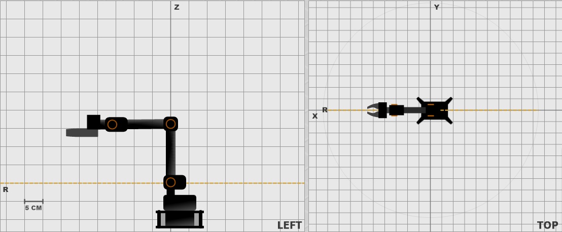
Side View
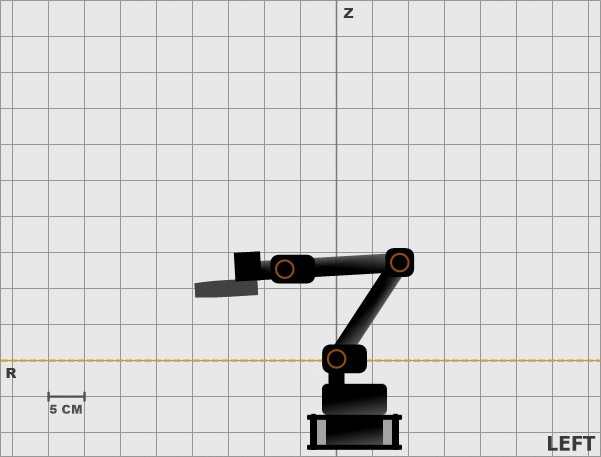
The left view is a representation {more to come|
Top View
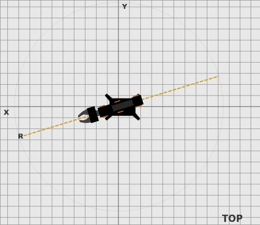
The top view shows the arm {more to come}
Left Menu
Gripper
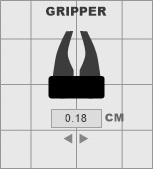
The gripper and wrist rotate can be controlled from this menu
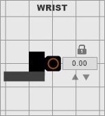
Wrist
End Effector Position
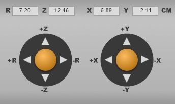
The position of the end effector can be controlled either by manually entering the information for R (radius), or x,y,z coordinate, or using the arrows.
Data Log
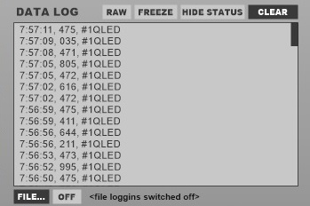
The console will be used as a serial command interface to manually send commands to the bus.
Sequencer
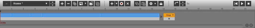
The sequencer allows the user to record sequences. From left to right:
Sequence association
{Work in progress}

Downloads
Download LSS Flowarm 3.0.8.12 here.
Password: beta
BETA: Note that information described here is subject to change, and is available for BETA testers.
{Work in progress}