
Mini Inline Hexapod Body Assembly Instructions Rev. 1.2
Mini Inline Hexapod Body Assembly Instructions Rev. 1.2
Updated February 2015
Safety first! Wear eye protection and never touch a powered robot!
Available Kit Versions
- MH2U with BotBoarduino microcontroller and SSC-32
- MH2U with BotBoarduino microcontroller and SSC-32U
- MH2F with SSC-32 and Bluetooth (FlowBotics)
- MH2F with SSC-32U and Bluetooth (FlowBotics)
- MH2 with SSC-32 and Bot Board 2 microcontroller (old model)
Take note of which version you have and follow each step accordingly, as the connections and configuration are different. Since the Bot Board 2 + Basic Atom is an older model, please follow the BotBoarduino procedure unless indicated otherwise.
Note: Loctite / thread lock can be used on aluminum components, though it is not necessary if the nuts are properly tightened. Do not use thread lock with Lexan or plastic as it may cause damage.
The lexan pieces have a protective covering that needs to be removed before assembly. When the laser cuts, the covering melts into the cut edge which can make removal difficult. If you gently scrape the cut edge with a flat blade screwdriver, the covering can easily be lifted and peeled off.
On smaller pieces the coverings can be more difficult to remove. If you have trouble you can gently scrape the cut edge, then use duct tape to lift the covering off.
For further information on lexan, see this page.
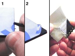 Lexan Preparation.
Before assembling, read and understand the relevant user guide for your kit:
- SSC-32: SSC-32 User Guide
- SSC-32U: SSC-32U User Guide
- BotBoarduino: BotBoarduino User Guide
The MH2 + BotBoarduino uses the Arduino software from www.arduino.cc. Sample code on GitHub uses a Lynxmotion PS2 controller as input (sold separately).
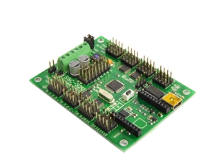 Figure 1 (SSC-32U shown as example).
Install both boards to the top Lexan plate using eight 4-40 x 1/4" hex socket screws to attach the spacers. The "top" plate has a cutout for the servo (the servo cutout is the "front" of the robot), while the bottom only has cutouts and is symmetric.
If you have a kit which includes only the SSC-32 or SSC-32U (as with FlowBotics), use four 4-40 x 1/4" hex socket screws to attach the spacers to the top body plate.
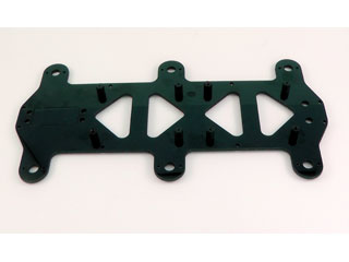 Figure 2a.
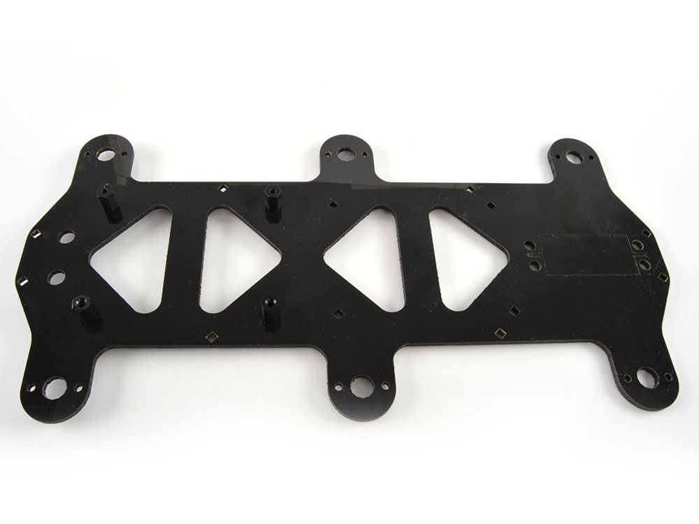 Figure 2b (top of top plate).
Flip the plate over and use eight 4-40 x 1/4" hex socket screws to attach the long aluminum spacers to the underside of the top body plate. This applies to both kit variants (2a and 2b).
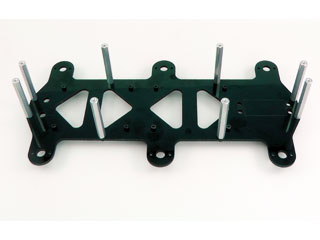 Figure 3a (underside of top plate).
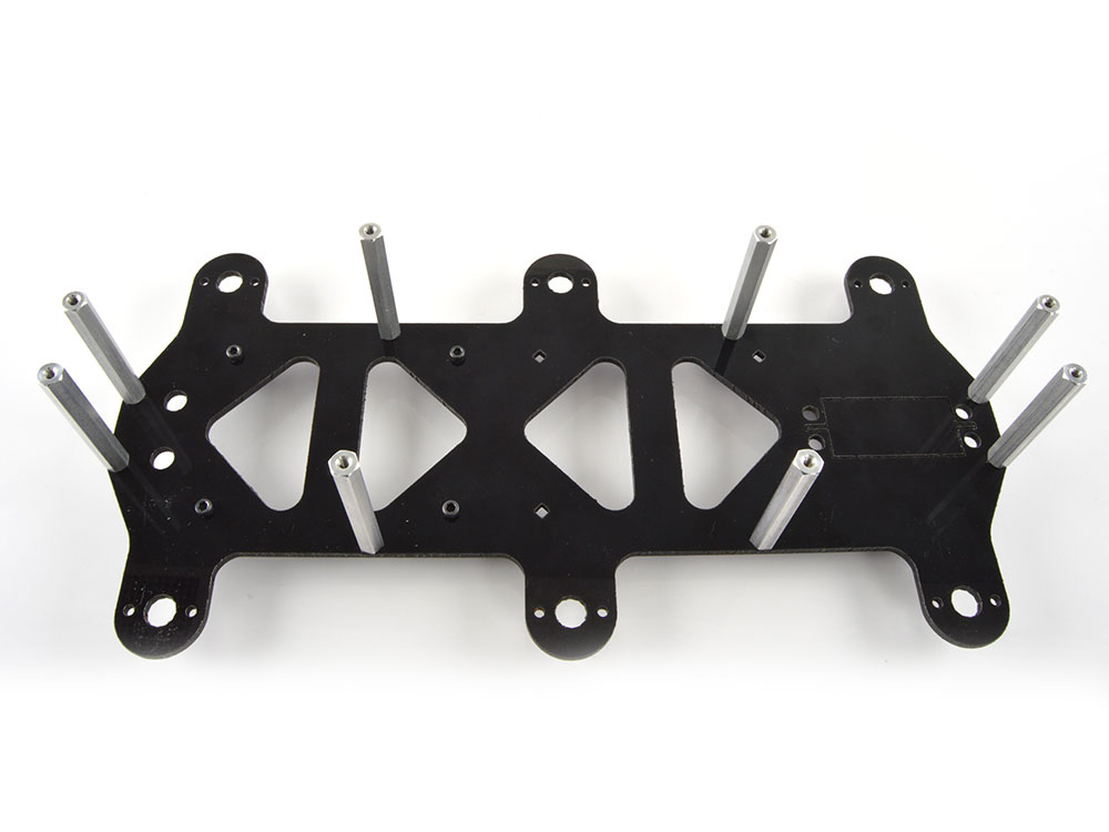 Figure 3b (underside of top plate).
Mount the bottom of the robot to the top using eight 1/4" hex screws.
Note: it would be a good idea to install the battery into the chassis at this point before connecting the bottom plate. Place the battery in the center of the chassis with the wire closest to the rear of the bot. You can use velcro, double sided tape or tie-wraps to hold it in place.
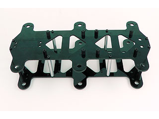 Figure 4a (BotBoarduino w/ SSC-32 / 32U).
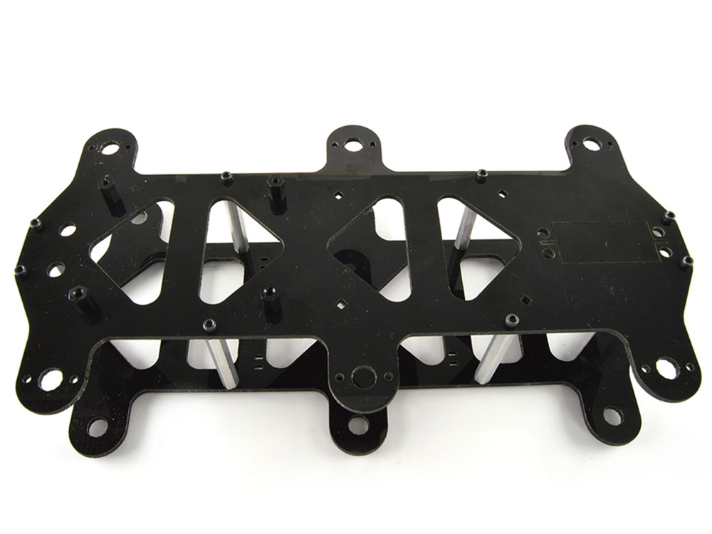 Figure 4b (SSC-32 / 32U alone).
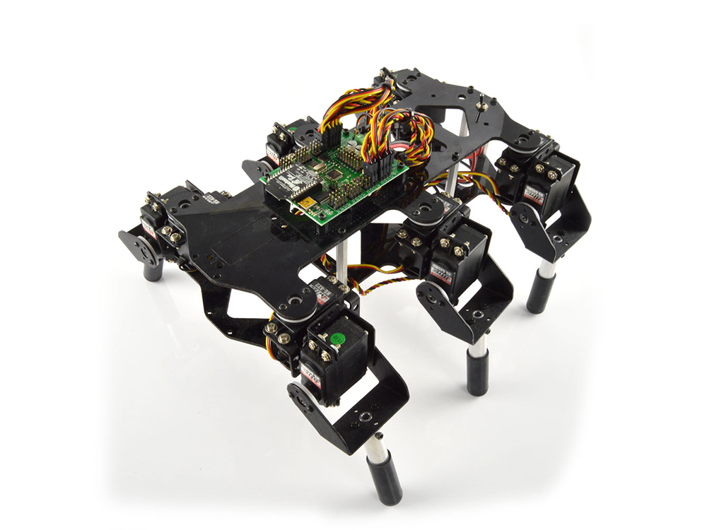
Attach the legs assembled in the Mini 2DoF Leg guide as shown, making sure to use right or left legs as indicated. If a servo horn moved from center during assembly, re-center it before installing. Orientation is important — pay close attention to the photo. The "front" of the robot has the cutout for a servo (sold separately).
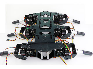 Figure 5.
Use a 2mm wide flat blade screwdriver when inserting wires into the SSC-32, SSC-32U and/or BotBoarduino terminals. Rotate the screw both directions looking into the end of the terminal. When you see it opening, keep turning until it is open completely. Wrap/twist the wires by hand to ensure they are aligned as in Figure 6.
Be sure that the wires are fully inserted and that no stray wires can touch each other — a short can cause the battery to discharge rapidly, causing heat and possibly fire.
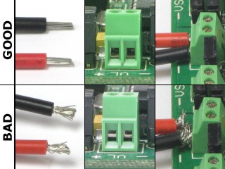 Figure 6.
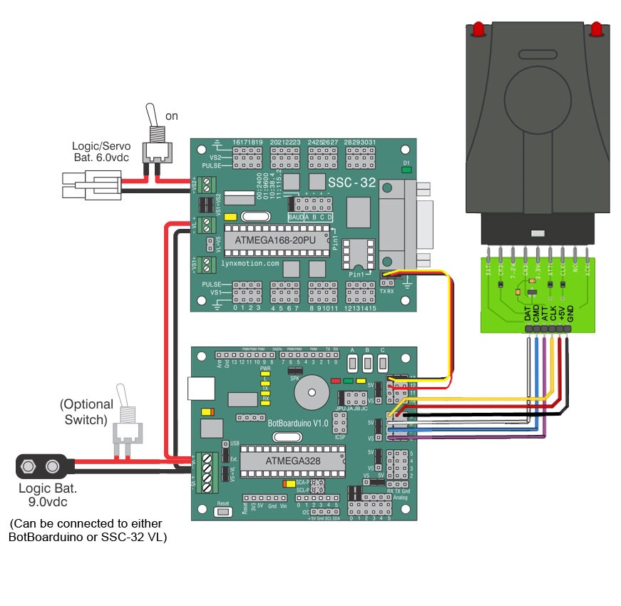
Install both boards into the chassis using eight 1/4" hex screws. Orient the board with the connector facing the servo cutout. Connect the loose power cable from the SSC-32's VL terminal to the Bot Board II's VL terminal. Attach the BotBoarduino and secure using four 1/4" hex screws. Install the power switch(es) at the rear. Do not connect the servos yet.
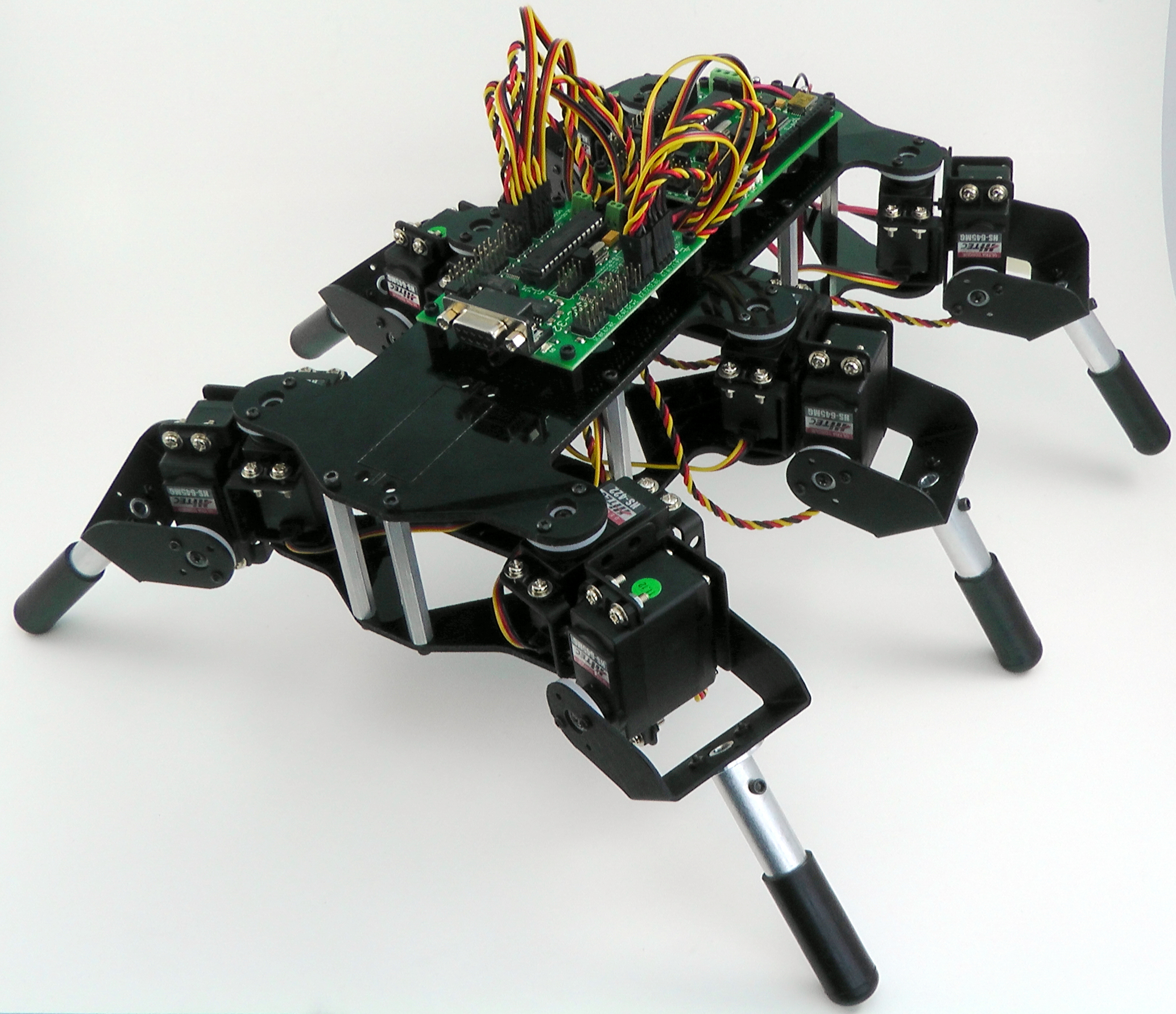 Figure 7 (SSC-32 + BotBoarduino shown).
Double check your connections against the schematic. Be sure red wires go to positive (+) and black wires to negative (−). Note that the VL=VS jumper on the SSC-32 is removed, as are the Tx and Rx jumpers. The wiring from SSC-32's Tx/Rx pins to the BotBoarduino's pins are NOT in line — the red/center/power pin needs to be removed and connected to pin 12 on the BotBoarduino.
| Servo Letter Definitions (Bot Board + SSC-32 + PS2 V1) | ||
|---|---|---|
| Left Right |
Rear Middle/Center Front |
Vertical Horizontal |
Bot Board 2 + Basic Atom + SSC-32
- SSC-32: VL terminal connected to 9V battery (red to +, black to −)
- SSC-32: VS1 terminal connected to the switch (red to +, black to −)
- SSC-32: VL = VS jumper is REMOVED
- SSC-32: VS1 = VS2 jumpers left in place
- Bot Board 2: Take note of the jumpers
- Bot Board 2: Power from SSC-32 using extra wires (red to +, black to −)
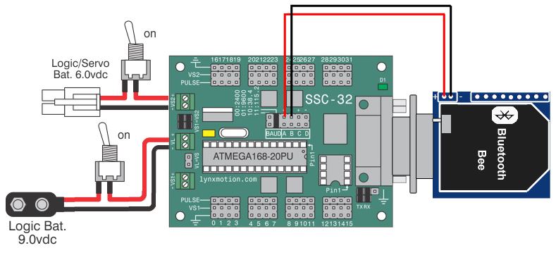
SSC-32 + Bluetooth Bee
- VL terminal connected to 9V battery (red to +, black to −)
- VS1 terminal connected to the switch (red to +, black to −)
- VL = VS jumper is REMOVED
- VS1 = VS2 jumpers left in place
- Baud rate jumpers set to 9600
- Bluetooth Bee connected to breakout board as shown
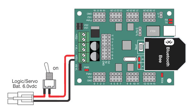
SSC-32U + Bluetooth Bee
- VS1 terminal connected to 6V battery switch (red to +, black to −)
- VL = VS jumper is in place
- VS1 = VS2 jumpers left in place
- Baud rate set to 9600
- Bluetooth Bee connected to board as shown
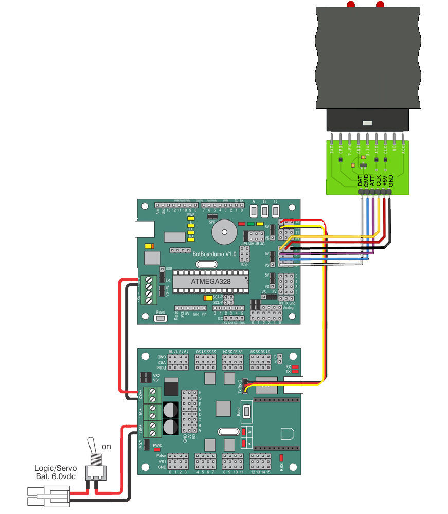
BotBoarduino + SSC-32U + PS2v3
- VL terminal connected to 9V battery (red to +, black to −)
- VS1 terminal connected to the switch (red to +, black to −)
- VL = VS jumper is REMOVED
- VS1 = VS2 jumpers left in place
- Baud rate jumpers set to 9600
BotBoarduino + SSC-32 + PS2v2
- VL terminal connected to 9V battery (red to +, black to −)
- VS1 terminal connected to the switch (red to +, black to −)
- VL = VS jumper is REMOVED
- VS1 = VS2 jumpers left in place
Plug the servos into the SSC-32 or SSC-32U as indicated in Table 8. Simply plug in the servo associated with the function to the corresponding pin. Be sure the black wire is near the outside of the board and the yellow wire is near the center of the board. Proper cable routing can be done later.
| 0 | Right Rear Vertical | 16 | Left Rear Vertical |
| 1 | Right Rear Horizontal | 17 | Left Rear Horizontal |
| 2 | Right Center Vertical | 18 | Left Center Vertical |
| 3 | Right Center Horizontal | 19 | Left Center Horizontal |
| 4 | Right Front Vertical | 20 | Left Front Vertical |
| 5 | Right Front Horizontal | 21 | Left Front Horizontal |
Connect a 9V battery to the battery clip and turn the On/Off switch to ON. You should see the green LED on the SSC-32 and the power LED on the Bot Board 2 or BotBoarduino switch on.
If these LEDs do not switch on, immediately power off your robot and double check your connections.
Turn the 9V switch to OFF. Connect the 6VDC battery pack to power the servos. Flip the switch to turn servo power on. The LEDs should NOT switch on this time. If they do, immediately power off and double check your connections.
Note: battery packs do NOT come charged. Charge before proceeding to the next tutorial.
Connect the 6VDC battery pack to power both the servos and electronics. Flip the switch to turn servo power on. The LEDs should NOT switch on. If they do, immediately power off and double check your connections.
Note: battery packs do NOT come charged. Charge before proceeding.
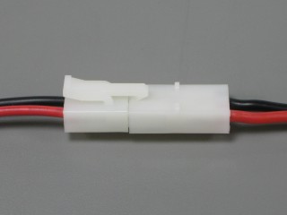 Figure 9.
Now that the robot is assembled, proceed with calibration and programming:
- MH2F with SSC-32 + Bluetooth (FlowBotics): Install and open FlowBotics Studio and follow the instructions
- MH2F with SSC-32U + Bluetooth (FlowBotics): Install and open FlowBotics Studio and follow the instructions*
- MH2 with SSC-32 + Bot Board 2 (old model): Programming Guide
* Note that the Bluetooth button within the project needs to be pressed to change the baud rate to 9600.
 Completed MH2 (SSC-32U shown).
Connect the 6VDC battery pack to power the servos. Flip the switch to turn servo power on. Applies to:
- MH2U with BotBoarduino + SSC-32
- MH2U with BotBoarduino + SSC-32U
To calibrate the servos, use Lynxterm and connect to the SSC-32 / 32U directly.
Download and install the Arduino IDE from www.arduino.cc. Sample code for the MH2 is available on the Lynxmotion GitHub page.
Alternatively, the MH2 can use the SSC-32 / SSC-32U's built-in hexapod sequencer.
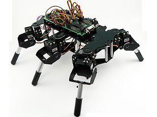 Completed MH2.