
H3-R Body Assembly Instructions v5.0
H3-R Body Assembly Instructions Rev. 5
Updated January 27, 2009
Safety first! Wear eye protection and never touch a powered robot!
The purpose of this guide is to construct the chassis, attach the legs, and install the electronics. As long as the servo horns have not been removed from the servos, you do not have to center them during the assembly process.
Note: This document shows the BH3-R in the images. The procedure is the same for all kits.
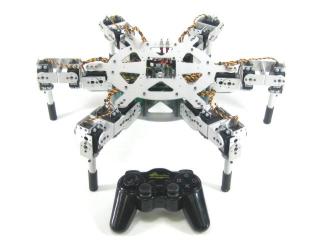
AH3-R.
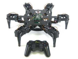
BH3-R.
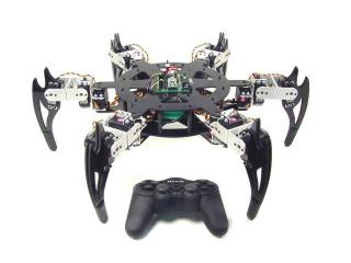
CH3-R.
Use the 4-40 x 1/4" hex socket screws to attach the spacers to the underside of the top panel.
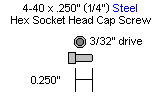
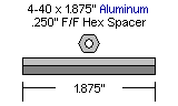
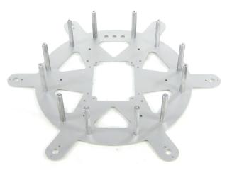 Figure 1.
Use the 4-40 x 1/4" hex socket screws to attach the bottom panel to the spacers. Note: the bottom panel is symmetrical — there is no front or back.
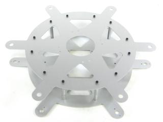 Figure 2.
The SSC-32 should be configured for 115.2 kbaud and DB9 communication, with the VS2=VS1 jumper installed. Remove the VL=VS jumper. Consult the SSC-32 manual if needed. Attach the wiring harness to VS1. Connect 8" of 24AWG wire (not included) AND the 9V battery clip to VL to provide power for the electronics. For now, put electrical tape on the end of the wire. Make sure red wires go to (+) and black wires go to (−). Using four 4-40 x 3/8" hex socket screws, attach the 1.0" hex spacers to the board as shown.

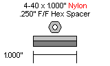
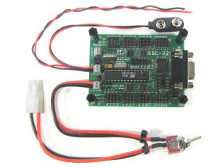 Figure 3.
Schematic. Double check your connections against the schematic below.
| Servo Letter Definitions | ||
|---|---|---|
| Left Right |
Rear Middle Front |
Knee Vertical Horizontal |
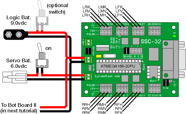
Schematic 3-1.
Slip the SSC-32 in through the hole in the top of the robot and use four 4-40 x 3/8" hex socket screws to attach the board as shown. Make sure the DB9 port is at the front of the robot, opposite the power switch hole! This ensures you can easily plug in the servo cables. Install the power switch in the power switch hole at the rear of the robot.
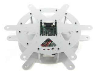 Figure 4.
Install all the legs. Refer to Figure 5 for clarification.
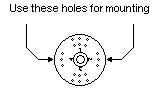
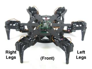 Figure 5.
Plug the servos into the SSC-32 as illustrated in Figure 6. Simply plug in the servo associated with the function to the corresponding pin. If oriented correctly, the I/O port (group of four pins) will be closest to its corresponding leg.
Refer to Schematic 3-1 for detailed information.
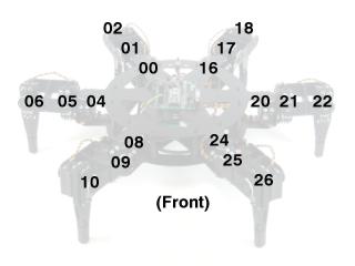 Figure 6.
This completes the mechanical assembly. You can now move on to the Complete H3/H3-R Tutorial.
Figure 7.