
Phoenix Bot Board II / BASIC Atom Pro Tutorial
Phoenix Bot Board II / BASIC Atom Pro Tutorial
Updated August 10, 2010. Phoenix code v2.0
Safety first! Wear eye protection and never touch a powered robot!
Note: This tutorial applies to the SSC-32 v2 with GP firmware.
Required Software: Basic Micro Studio | Basic Atom Pro program
Place the robot on top of a CD spindle or similar to hold the legs off the ground.
Download and install LynxTerm. Connect the SSC-32 to the serial port and apply power. The green LED should light and stay on until it receives a valid serial command. Run the LynxTerm program.
Please consult the serial troubleshooting guide if you have difficulties.
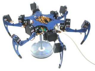 Figure 1.
Download the 2.04GP Beta firmware or higher. Remove power from the SSC-32 and make sure the baud rate is set to 115.2k. Refer to the manual for baud rate information.
Apply power again, ensure it's connected to the PC, and click "Firmware" at the bottom of the LynxTerm screen. Click "Open" and browse to the firmware file. Click "Begin Update".
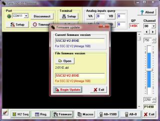 Figure 3.
When the firmware has been successfully updated, click "Ok" then "Exit". Do the "ver" test: type "ver" into the terminal and press Enter. You should see the proper firmware version returned.
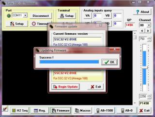 Figure 4.
Place the robot in a position as close to neutral as possible. Click "All=1500" in the bottom right portion of the screen. The robot should go to and hold the neutral position, resembling Figures 7, 8, and 9. If joints are off by more than 15°, remove the center screw from the round servo horn, pull the horn off, rotate until aligned, then reattach.
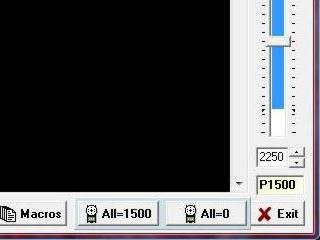 Figure 5.
From the main screen, click "Reg" to open the Registers page. Click "Default" to initialize default values.
Do the most accurate alignment as possible! The robot can only operate as well as it is aligned. A poorly aligned robot will walk poorly.
Refer to the servo channel number guide (Figure 6) for the following alignment steps.
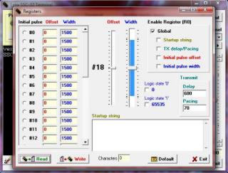 Figure 6.
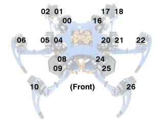 Servo Channel Numbering.
Adjust the robot's horizontal hip servos. Select servo #0, then adjust the "Offset" slider until the tibia is in line with the horizontal hip servo horn's screws as shown.
Do this for servos #00, 04, 08, 16, 20, 24.
Note: the mouse scrollwheel or keyboard arrow keys can be used for fine adjustments.
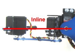 Figure 7.
Adjust the robot's vertical hip servos. Select servo #1, then adjust the "Offset" slider until the robot's femur is parallel to the ground as shown.
Do this for servos #01, 05, 09, 17, 21, 25.
 Figure 8.
Adjust the robot's knee servos. Select servo #2, then adjust the "Offset" slider until the tip of the robot's foot is directly underneath the knee servo pivot point — from the pivot point to the tip of the foot should be perpendicular to the ground as shown.
Do this for servos #02, 06, 10, 18, 22, 26.
 Figure 9.
Enable "Initial Pulse Offset", then click "Write" and exit LynxTerm when the write process is finished.
Note: you can also check "Initial Pulse Width" to automatically enable the servos on power-up. If you do, make sure you click "Write" to save the changes.
This completes the Phoenix configuration for the SSC-32 registers. Whenever the robot is turned on, the servos will automatically be aligned and/or enabled.
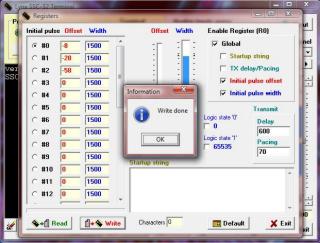 Figure 10.
Remove a screw holding the SSC-32's standoffs onto the Phoenix chassis. Replace the screw with the 3/8" M/F standoff as shown. Be careful not to over-tighten. Repeat for the remaining three screws.
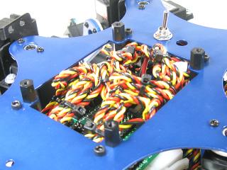 Figure 11.
Flip the Phoenix over and attach the PS2 cable's receiver socket as shown. Route the rest of the cable up and out the top.
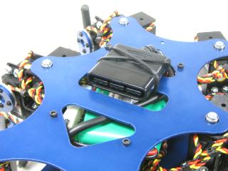 Figure 12.
Modify a 6" servo extender cable by removing the header pins so you have two female ends. Use an exacto knife to gently pry the tab up to pull the red wire free on one end. Cover the exposed connector with heat shrink to avoid accidental shorts.
Remove the TX and RX jumpers from the lower-right corner of the SSC-32 and plug the unmodified end of the cable in: yellow on TX, red on RX, black on ground.
Plug in extra lengths of 18–24AWG wires to VL on the SSC-32 with the 9VDC battery clip — these will power the Bot Board II.
See Tables 14-1 through 14-3 and Schematic 14-3 for connection information.
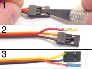 Figure 13.
Install the Bot Board II using 1/4" socket head screws. Plug the modified servo cable end in: yellow and black wires on pin 10 with black toward the outside, red wire on pin 11 toward the center.
Plug in the PS2 cable as shown in Figure 14-2. Plug in the power wires from the SSC-32 to VL.
Note: refer only to Figure 14-2 for connection information — cable colors may be outdated. A complete listing of possible colors is available here.
Install the BASIC Atom Pro as shown in the orientation diagram.
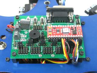 Figure 14-1.
 Figure 14-2.
SSC-32 Connection Information (Table 14-1)
| What | Where |
|---|---|
| Jumper installed | VS1=VS2 |
| Jumper installed | 38.4 Baud Rate |
| Unmodified Cable End | TX / RX / GND (Black on GND) |
| 9VDC Battery Clip | VL |
| Power Wires | VL to BBII's VL |
| Battery Wiring Harness | VS1 |
Bot Board II Connection Information (Table 14-2)
| What | Where |
|---|---|
| Power Wires | SSC-32's VL to VL |
| Modified Cable — Black & Yellow | Pin 10, Black toward outside |
| Modified Cable — Red wire | Pin 11, toward center |
| Power jumper for I/O 12-15 | 5VDC |
| PS2 Cable | I/O Group 12-15 |
Servo Channels (Table 14-3)
| Label / Ch. | Function | Label / Ch. | Function |
|---|---|---|---|
| RRH / 00 | Right Rear Horizontal Hip | LRH / 16 | Left Rear Horizontal Hip |
| RRV / 01 | Right Rear Vertical Hip | LRV / 17 | Left Rear Vertical Hip |
| RRK / 02 | Right Rear Knee | LRK / 18 | Left Rear Knee |
| RMH / 04 | Right Middle Horizontal Hip | LMH / 20 | Left Middle Horizontal Hip |
| RMV / 05 | Right Middle Vertical Hip | LMV / 21 | Left Middle Vertical Hip |
| RMK / 06 | Right Middle Knee | LMK / 22 | Left Middle Knee |
| RFH / 08 | Right Front Horizontal Hip | LFH / 24 | Left Front Horizontal Hip |
| RFV / 09 | Right Front Vertical Hip | LFV / 25 | Left Front Vertical Hip |
| RFK / 10 | Right Front Knee | LFK / 26 | Left Front Knee |
Schematic — Figure 14-3.
Download Basic Micro Studio and install and run the IDE to allow programming the chip.
Connect the serial data cable to the PC's serial port (9 pins that stick out) and the other end to the Bot Board's DB9 port. A BAFO BF-810 or IOGear USB-to-Serial adapter can also be used.
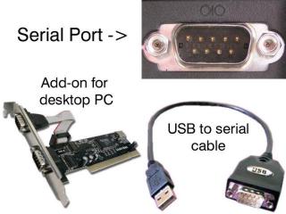 Figure 15.
Download the .zip file and unzip it. Open the .prj file in Studio (File → Open → *.prj) and verify the files are in the order shown in Table 16. Install the PS2 controller receiver, make sure the controller is on, then apply power. Program the Atom Pro. You should hear a beep after power up. Press Start and the legs should snap to position.
Note: the software switches the controller to analog mode, but some controllers may need this done manually. Continuous beeping means the PS2 controller is not connected. Try pressing Reset on the Bot Board II.
Table 16 — Programs
| Phoenix: phoe2ps2.zip | |
|---|---|
| phoenix_V20.prj | phoenix_cfg.bas | phoenix_V20.bas | phoenix_control_ps2.bas | |
| CH3-R: ch3r2ps2.zip | |
| phoenix_V20.prj | ch3-r_cfg.bas | phoenix_V20.bas | phoenix_control_ps2.bas |
The default is Walking mode 1. Use the Left joystick to move without turning, and the Right joystick to rotate. D-Pad Up/Down adjusts body height. Triangle switches between 35mm walking height and lowered position. L1, L2, Circle, and X trigger special body moves modes where joysticks change function — see Table 17 below.
| Button | Function |
|---|---|
| Common Controls | |
| Start | Turn robot on/off |
| R3 | Switch Walk mode 1 / 2 |
| L1 | Toggle Shift mode |
| L2 | Toggle Rotate mode |
| X | Toggle GP Player mode |
| O Circle | Toggle Single Leg mode |
| □ Square | Toggle Balance mode |
| △ Triangle | Switch 35mm height / lowered |
| D-Pad Up | Body up 10mm |
| D-Pad Down | Body down 10mm |
| D-Pad Left | Decrease speed by 50mS |
| D-Pad Right | Increase speed by 50mS |
| Walk Mode Controls (default) | |
| Select | Change gaits |
| Left Joystick | Mode 1: Walk/strafe | Mode 2: Disabled |
| Right Joystick | Mode 1: Rotate | Mode 2: Walk/rotate |
| R1 | Toggle double gait travel speed |
| R2 | Toggle double gait travel length |
| Button | Function |
|---|---|
| Shift Mode Controls | |
| L1 | Turn Shift mode off |
| Left Joystick | Shift body X/Z |
| Right Joystick | Shift and rotate body Y |
| Rotate Mode Controls | |
| L2 | Turn Rotate mode off |
| Left Joystick | Rotate body X/Z |
| Right Joystick | Rotate body Y |
| Single Leg Mode Controls | |
| O Circle | Turn Single Leg mode off |
| Select | Switch legs |
| Left Joystick | Move leg X/Z (relative) |
| Right Joystick | Move leg Y (absolute) |
| R2 | Hold/release leg position |
| GP Player Mode Controls | |
| X | Turn GP Player mode off |
| Select | Switch sequences |
| R2 | Start sequences |
PS2 Controls — Table 17.
For Phoenix or CH3-R with DIY controller — information on the DIY controller is located on the Lynxmotion forum.
Download the .zip file and unzip it. Open the .prj file in Studio and verify files are in the order shown in Table 18. Program the Atom Pro, then apply power. You should hear a beep after power up. Press Start and the legs should snap to position. Remove power when confirmed.
Table 18 — Programs
| Phoenix: phoe2diy.zip | |
|---|---|
| phoenix_V20.prj | phoenix_cfg.bas | phoenix_V20.bas | phoenix_control_diy-rc.bas | |
| CH3-R: ch3r2diy.zip | |
| phoenix_V20.prj | ch3-r_cfg.bas | phoenix_V20.bas | phoenix_control_diy-rc.bas |
Use the Left joystick to control body height and rotation. The Right joystick handles walking and strafing. Buttons B, C, and D trigger special body moves modes — press A to return to normal Walking mode. See Table 19 below.
| Button | Function |
|---|---|
| Common Controls | |
| 0 | Turn robot on/off |
| A | Walk mode |
| B | Translate mode |
| C | Rotate mode |
| D | Single Leg mode |
| E | Toggle Balance mode |
| Left Slider | Speed |
| Right Slider | Leg lift height |
| Walk Mode Controls | |
| 1–8 | Switch gaits |
| Left Joystick | Body height / rotate |
| Right Joystick | Walk / strafe |
| Button | Function |
|---|---|
| Translate Mode Controls | |
| B | Turn Translate mode off |
| Left Joystick | Body height / Rotate body Y |
| Right Joystick | Translate body X/Z |
| Rotate Mode Controls | |
| C | Turn Rotate mode off |
| Left Joystick | Body height / Rotate body Y |
| Right Joystick | Rotate body X/Z |
| Single Leg Mode Controls | |
| D | Turn Single Leg mode off |
| 1–6 | Switch legs |
| Left Joystick | Move tars Y |
| Right Joystick | Move tars X/Z |
DIY Controls — Table 19.