
Humanoid Biped Arm Pair Assembly Guide
Humanoid Biped Arm Pair Assembly Guide
Updated August 30, 2007
Hardware: 3x Multi-Purpose Servo Bracket Two Pack (ASB-04) · 1x "L" Connector Bracket Two Pack (ASB-06) · 1x "C" Servo Bracket w/ Ball Bearings Two Pack (ASB-09) · 1x Offset Servo Bracket w/ Ball Bearings Two Pack (ASB-11) · 1x Aluminum Tubing Connector Hub pair (HUB-08) · 2x Aluminum Tubing 3.0" (AT-02) · 1x Rubber End Cap .500" x 1.50" Pair (REC-06) · 6x HS-5645 Digital Standard Servo (S5645MG)
Goal: Assemble a pair of humanoid biped arms using servo brackets, aluminum tubing, and a Little Grip.
Notes: This guide covers one arm for the robot's right side. Repeat all steps as a mirror image for the left side. This is only an example — there are countless other configurations with fewer degrees of freedom, no tubing, etc.
Humanoid Biped with Arms.
Attach two multi-purpose servo brackets together as shown using two 2-56 x .250" screws and 2-56 nuts.
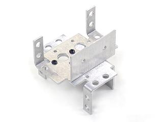 Figure 1.
Connect the offset "C" bracket to a multi-purpose bracket as shown. Refer to Figure 2-1 for ball bearing detail.
Figure 2-1 — Ball bearing detail.
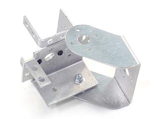 Figure 2-2.
Attach two servos as shown using the included 3mm hardware and two #2 tapping screws each. Rivet fasteners (NSRF-01, sold separately) can be used for quick prototype assembly.
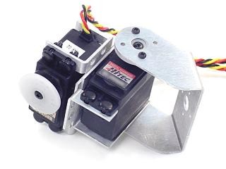 Figure 3.
Attach a "C" bracket as shown using four #2 tapping screws.
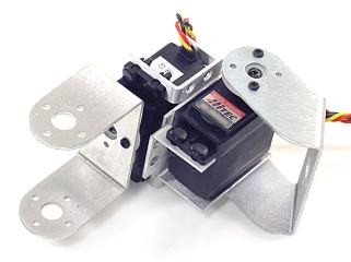 Figure 4.
Connect the "C" bracket to a multi-purpose bracket as shown. Refer to Figure 5-1 for ball bearing detail.
Figure 5-1 — Ball bearing detail.
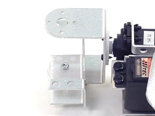 Figure 5-2.
Attach a tubing connector hub to an "L" connector bracket, then attach the "L" bracket to the multi-purpose bracket as shown using four 2-56 x .250" screws and 2-56 nuts.
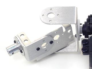 Figure 6.
Attach a servo as shown using the included 3mm hardware and two #2 tapping screws. Rivet fasteners (NSRF-01, sold separately) can be used for quick prototype assembly.
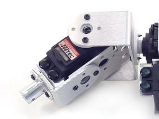 Figure 7.
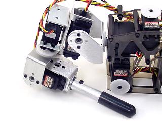
Connect the 3.0" aluminum tube to the hub using a 4-40 x .250" hex socket screw. Push the rubber end cap onto the free end of the tube.
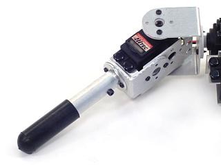 Figure 8.
Attach the offset "C" bracket to the shoulder servo as shown using two #2 tapping screws. This completes one arm — repeat all steps as a mirror image for the left arm.
Figure 9 (completed arm).