
Scout Biped 6DOF Alum. Leg Pair Assembly Guide
6DOF Biped Scout Alum. Leg Pair Assembly Guide
Updated June 5, 2006
Safety first! Wear eye protection and never touch a powered robot!
Note: Do not use Loctite or thread locks on the Lexan components — they are not necessary and may cause damage.
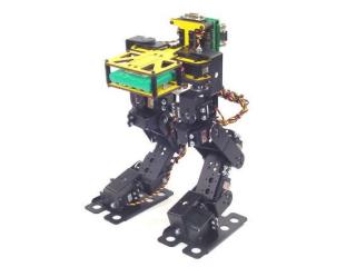
Completed Biped Scout.
Place the torso upside-down and insert two hip rotate servos into the servo holes as shown. Use eight snap rivet fasteners to secure them. Note: these snap rivet fasteners are included in the torso kit, not the leg kit.
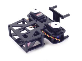 Figure 1.
Flip the torso assembly over. Attach two servo hinges to the servos, aligning the pivot points with the servo horns. Use the screws to attach the ball bearings flange-side down to the servo hinges.
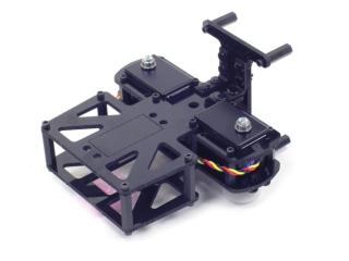 Figure 2.
Center the servos and attach two short "C" brackets to each side as shown using four #2 tapping screws. Tip: remove the ball bearing and push it into the "C" bracket before slipping it over the servo for easier assembly.
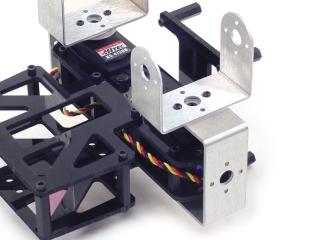 Figure 3.
Attach two multi-purpose brackets to the "C" brackets as shown. Refer to Figure 4-1 for ball bearing detail.
Figure 4-1 — Ball bearing detail.
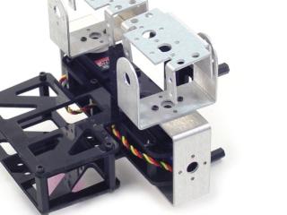 Figure 4-2.
Attach two more multi-purpose brackets to the ones already installed using four 2-56 screws and nuts.
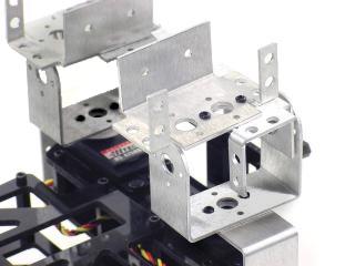 Figure 5.
Use four 2-56 screws and nuts to attach two short "C" brackets to two long "C" brackets.
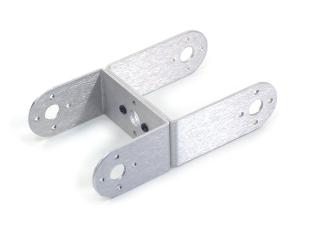 Figure 6.
Attach the short "C" bracket side of the shin assembly to the multi-purpose brackets as shown. Refer to Figure 7-1 for ball bearing detail.
Figure 7-1 — Ball bearing detail.
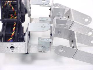 Figure 7-2.
Attach two dual-inline multi-purpose brackets to the long "C" brackets as shown. Refer to Figure 8-1 for ball bearing detail.
Figure 8-1 — Ball bearing detail.
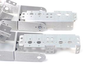 Figure 8-2.
Attach the ankle brackets to the feet brackets as shown using six 2-56 countersunk screws and 2-56 nuts.
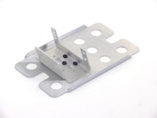 Figure 9.
Attach a short "C" bracket to the left foot ankle bracket as shown. Make a mirror image for the right foot. Refer to Figure 10-1 for ball bearing detail.
Figure 10-1 — Ball bearing detail.
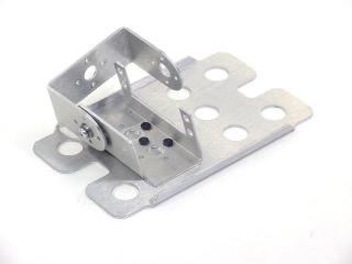 Figure 10-2.
Slip a foot rotate servo into the ankle bracket and attach using the servo-attachment hardware. Centre the servo. Use #2 tapping screws to attach a short "C" bracket on top of the other as shown in Figure 11-2.
Figure 11-1 — Bracket orientation.
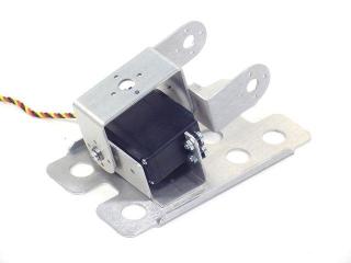 Figure 11-2.
Attach the foot assembly to the leg assembly as shown. Refer to Figure 12-1 for ball bearing detail.
Figure 12-1 — Ball bearing detail.
 Figure 12-2.
Install the hip x-axis servos. With servos centred, the legs should resemble Figure 13.
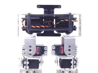 Figure 13.
Install the remaining six y-axis servos (hip, knee, and ankle for each leg). With servos centred, the legs should resemble Figure 14.
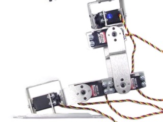 Figure 14.
Remove the centre screw from the hip servos, pull the bracket off, and rotate it counter-clockwise 30°. The Hitec servo spline has 24 teeth — 15° per click (2 clicks = 30°).
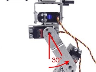 Figure 15.
Remove the centre screw from the knee servos, pull the bracket off, and rotate it clockwise 30°. The Hitec servo spline has 24 teeth — 15° per click (2 clicks = 30°).
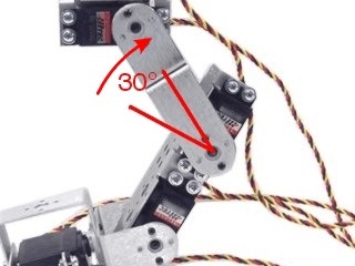 Figure 16.
Remove the centre screw from the ankle servos, pull the bracket off, and rotate it clockwise 45°. The Hitec servo spline has 24 teeth — 15° per click (3 clicks = 45°).
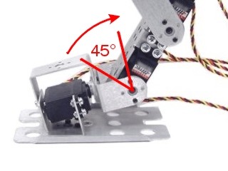 Figure 17.
When completed with all servos centred, your robot should resemble Figure 18.
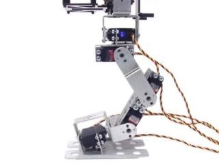 Figure 18.
If using only the SSC-32 (without Bot Board), install it with the pins facing inward as shown using four 4-40 x 1/4" screws.
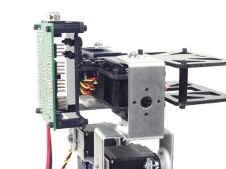 Figure 19.
If using both SSC-32 and Bot Board: install the SSC-32 using four 3/8" M-F standoffs, then install the Bot Board on top using four 4-40 x 1/4" screws. Consult the Bot Board and SSC-32 manuals for powering options.
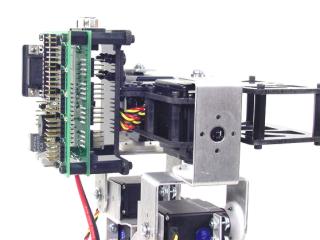 Figure 20.
Connect the servo wires per Table 21. Route wires to allow full leg range of motion — tie-wrapping wires to servo brackets is recommended. Note: X-axis = side to side; Y-axis = front to back.
| Robot's Right | SSC-32 Channel | Robot's Left | |
|---|---|---|---|
| Hip Rotate | 21 | 5 | Hip Rotate |
| Hip X | 20 | 4 | Hip X |
| Hip Y | 19 | 3 | Hip Y |
| Knee Y | 18 | 2 | Knee Y |
| Ankle Y | 17 | 1 | Ankle Y |
| Foot Rotate | 16 | 0 | Foot Rotate |
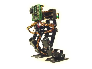
Figure 21 — Wired assembly.