
LSS - Communication Protocol
The Lynxmotion Smart Servo (LSS) protocol was created in order to be as simple and straightforward as possible from a user perspective, while at the same time trying to stay compact and robust yet highly versatile. Almost everything one might expect to be able to configure for a smart servo motor is available.
Session
A "session" is defined as the time between when the servo is powered ON to when it is powered OFF or reset.
Action Commands
Action commands are sent serially to the servo's Rx pin and must be set in the following format:
- Start with a number sign # (U+0023)
- Servo ID number as an integer
- Action command (one to three letters, no spaces, capital or lower case)
- Action value in the correct units with no decimal
- End with a control / carriage return '<cr>'
Ex: #5PD1443<cr>
Move servo with ID #5 to a position of 144.3 degrees.
Action commands cannot be combined with query commands, and only one action command can be sent at a time.
Action commands are session-specific, therefore once a servo is power cycled, it will not have any "memory" of previous actions or virtual positions (as described at the bottom of this page).
Action Modifiers
Two commands can be used as action modifiers only: Timed Move and Speed. The format is:
- Start with a number sign # (U+0023)
- Servo ID number as an integer
- Action command (one to three letters, no spaces, capital or lower case)
- Action value in the correct units with no decimal
- Modifier command (one letter)
- Modifier value in the correct units with no decimal
- End with a control / carriage return '<cr>'
Ex: #5P1456T1263<cr>
Results in the servo rotating from the current angular position to a pulse position of 1456 in 1263 milliseconds.
Modified commands are command specific.
Query Commands
Query commands are sent serially to the servo's Rx pin and must be set in the following format:
- Start with a number sign # (U+0023)
- Servo ID number as an integer
- Query command (one to three letters, no spaces, capital or lower case)
- End with a control / carriage return '<cr>'
Ex: #5QD<cr>Query position in degrees for servo #5
The query will return a value via the Tx pin with the following format:
- Start with an asterisk (U+002A)
- Servo ID number as an integer
- Query command (one to three letters, no spaces, capital letters)
- The reported value in the units described, no decimals.
- End with a control / carriage return '<cr>'
Ex: *5QD1443<cr>
Indicates that servo #5 is currently at 144.3 degrees.
Configuration Commands
Configuration commands affect the servo's current session* but unlike action commands, configuration commands are written to EEPROM and are retained even if the servo loses power (therefore NOT session specific). Not all action commands have a corresponding configuration and vice versa. Certain configurations are retained for when the servo is used in RC model. More information can be found on the LSS - RC PWM page.
- Start with a number sign # (U+0023)
- Servo ID number as an integer
- Configuration command (two to three letters, no spaces, capital or lower case)
- Configuration value in the correct units with no decimal
- End with a control / carriage return '<cr>'
Ex: #5CO-50<cr>
Assigns an absolute origin offset of -5.0 degrees (with respect to factory origin) to servo #5 and changes the offset for that session to -5.0 degrees.
Configuration commands are not cumulative, in that if two configurations are sent at any time, only the last configuration is used and stored.
*Important Note: the one exception is the baud rate - the servo's current session retains the given baud rate. The new baud rate will only be in place when the servo is power cycled.
Command List
| # | Description | Action | Query | Config | RC | Serial | Units | Notes |
|---|---|---|---|---|---|---|---|---|
| 1 | Limp | L | ✓ | none | ||||
| 2 | Halt & Hold | H | ✓ | none | ||||
| 3 | Timed move | T | ✓ | milliseconds | Modifier only | |||
| 4 | Speed | S | ✓ | microseconds / second | Modifier only | |||
| 5 | Move in Degrees (relative) | MD | ✓ | tenths of degrees (ex 325 = 32.5 degrees; 91 = 9.1 degrees) | ||||
| 6 | Origin Offset | O | QO | CO | ✓ | ✓ | tenths of degrees (ex 325 = 32.5 degrees; 91 = 9.1 degrees) | |
| 7 | Angular Range | AR | QAR | CAR | ✓ | ✓ | tenths of degrees (ex 325 = 32.5 degrees; 91 = 9.1 degrees) | |
| 8 | Position in Pulse | P | QP | ✓ | microseconds | See details below. | ||
| 9 | Position in Degrees | D | QD | ✓ | tenths of degrees (ex 325 = 32.5 degrees; 91 = 9.1 degrees) | |||
| 10 | Wheel mode in Degrees | WD | QWD | ✓ | tenths of degrees per second (ex 248 = 24.8 degrees per second) | |||
| 11 | Wheel mode in RPM | WR | QWR | ✓ | rpm | |||
| 12 | Speed in Degrees | SD | QSD | CSD | ✓ | ✓ | tenths of degrees per second (ex 248 = 24.8 degrees per second) | |
| 13 | Speed in RPM | SR | QSR | CSR | ✓ | ✓ | rpm | |
| 14 | Rigidity | R | QR | CR | ✓ | ✓ | none | |
| 15 | N/A (removed) | |||||||
| 16 | LED Color | LED | QLED | CLED | ✓ | ✓ | none (integer from 1 to 8) | 0=OFF 1=RED 2=GREEN 3= BLUE 4=YELLOW 5=CYAN 6= 7=MAGENTA, 8=WHITE |
| 17 | ID # | ID | QID | CID | ✓ | none (integer from 0 to 250) | Note: ID 254 is a "broadcast" which all servos respond to. | |
| 18 | Baud rate | B | QB | CB | ✓ | none (integer) | ||
| 19 | Gyre direction (G) | G | QG | CG | ✓ | ✓ | none | Gyre / rotation direction where 1= CW (clockwise) -1 = CCW (counter-clockwise) |
| 20 | First Position (Pulse) | QFP | CFP | ✓ | ✓ | none | ||
| 21 | First Position (Degrees) | QFD | CFD | ✓ | ✓ | none | ||
| 22 | Target (Degree) Position | QDT | ✓ | tenths of degrees (ex 325 = 32.5 degrees; 91 = 9.1 degrees) | ||||
| 23 | Model | QM | none (integer) | |||||
| 24 | Serial Number | QN | none (integer) | |||||
| 25 | Firmware version | QF | none (integer) | |||||
| 26 | Query (general status) | Q | ✓ | none (integer from 1 to 8) | ||||
| 27 | Voltage | QV | ✓ | tenths of volt (ex 113 = 11.3V; 92 = 9.2V) | ||||
| 28 | Temperature | QT | ✓ | degrees Celsius | ||||
| 29 | Current | QC | ✓ | tenths of Amps (ex 2 = 0.2A) | ||||
Details
1. Limp (L)
Example: #5L<cr>
This action causes the servo to go "limp". The microcontroller will still be powered, but the motor will not. As an emergency safety feature, should the robot not be doing what it is supposed to or risks damage, use the broadcast ID to set all servos limp #254L<cr>.
2. Halt & Hold (H)
Example: #5H<cr>
This action overrides whatever the servo might be doing at the time the command is received (accelerating, moving continuously etc.) and causes it to stop immediately and hold that position.
3. Timed move (T)
Example: #5P1500T2500<cr>
Timed move can be used only as a modifier for a position (P) action. The units are in milliseconds, so a timed move of 2500 milliseconds would cause the servo to rotate from its current position to the desired position in 2.5 seconds. This command is in place to ensure backwards compatibility with the SSC-32 / 32U protocol.
4. Speed (S)
Example: #5P1500S750<cr>
This command is a modifier only for a position (P) action and determines the speed of the move in microseconds per second. A speed of 750 microseconds would cause the servo to rotate from its current position to the desired position at a speed of 750 microseconds per second. This command is in place to ensure backwards compatibility with the SSC-32 / 32U protocol.
5. (Relative) Move in Degrees (MD)
Example: #5MD123<cr>
The relative move command causes the servo to read its current position and move the specified number of tenths of degrees in the corresponding position. For example if the servo is set to rotate CW (default) and an MD command of 123 is sent to the servo, it will cause the servo to rotate clockwise by 12.3 degrees. Negative commands would cause the servo to rotate in the opposite configured direction.
6. Origin Offset Action (O)
Example: #5O2400<cr>
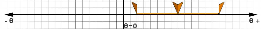
This command allows you to temporarily change the origin of the servo in relation to the factory zero position. The setting will be lost upon servo reset / power cycle. Origin offset commands are not cumulative and always relate to factory zero. Note that for a given session, the O command overrides the CO command. In the first image, the origin at factory offset '0' (centered).
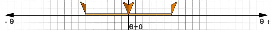
In the second image, the origina, as well as the angular range (explained below) have been shifted by 240.0 degrees:
Origin Offset Query (QO)
Example: #5QO<cr> Returns: *5QO-13
This allows you to query the angle (in tenths of degrees) of the origin in relation to the factory zero position.
Configure Origin Offset (CO)
Example: #5CO-24<cr>
This command allows you to change the origin of the servo in relation to the factory zero position in EEPROM. The setting will be saved upon servo reset / power cycle. Origin offset configuration commands are not cumulative and always relate to factory zero. The new origin is also used in RC mode.
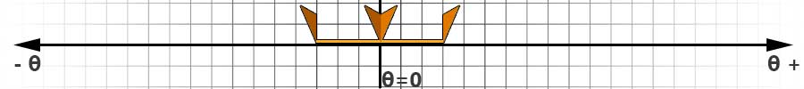
7. Angular Range (AR)
Example: #5AR1800<cr>
This command allows you to temporarily change the total angular range of the servo in tenths of degrees. This applies to the Position in Pulse (P) command and RC mode. The default for (P) and RC mode is 1800 (180.0 degrees total, or ±90.0 degrees). In the first image,
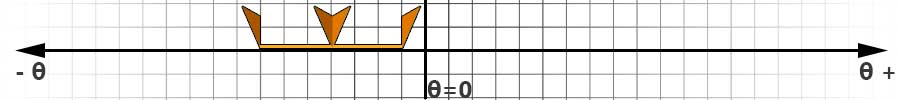
Here, the angular range has been restricted to 180.0 degrees, or -90.0 to +90.0. The center has remained unchanged.
The angular range action command (ex. #5AR1800<cr>) and origin offset action command (ex. #5O-1200<cr>) an be used to move both the center and limit the angular range:
Query Angular Range (QAR)
Example: #5QAR<cr> might return *5AR2756
Configure Angular Range (CAR)
This command allows you to change the total angular range of the servo in tenths of degrees in EEPROM. The setting will be saved upon servo reset / power cycle.
8. Position in Pulse (P)
Example: #5P2334<cr>
The position in PWM pulses was retained in order to be backward compatible with the SSC-32 / 32U protocol. This relates the desired angle with an RC standard PWM pulse and is further explained in the SSC-32 and SSC-32U manuals found on Lynxmotion.com. Without any modifications to configuration considered, and a ±90.0 degrees standard range where 1500 microseconds is centered, a pulse of 2334 would set the servo to 165.1 degrees. Valid values for P are [500, 2500]. Values outside this range are corrected to end points.
Query Position in Pulse (QP)
Example: #5QP<cr> might return *5QP
This command queries the current angular position in PWM "units". The user must take into consideration that the response includes any angular range and origin configurations in order to determine the actual angle.
Valid values for QP are {-500, [500, 2500], -2500}. Values outside the [500, 2500] range are given a negative corresponding end point value to indicate they are out of bounds.
9. Position in Degrees (D)
Example: #5PD1456<cr>
This moves the servo to an angle of 145.6 degrees, where the center (0) position is centered. Negative values (ex. -176 representing -17.6 degrees) are used. A full circle would be from -1800 to 1800 degrees. A value of 2700 would be the same angle as -900, except the servo would move in a different direction.
Larger values are permitted and allow for multi-turn functionality using the concept of virtual position.
Query Position in Degrees (QD)
Example: #5QD<cr> might return *5QD0<cr>
10. Wheel Mode in Degrees (WD)
Ex: #5WD900<cr>
This command sets the servo to wheel mode where it will rotate in the desired direction at the selected speed. The example above would have the servo rotate at 90.0 degrees per second clockwise (assuming factory default configurations).
Query Wheel Mode in Degrees (QWD)
Ex: #5QWD<cr> might return *5QWD900<cr>
The servo replies with the angular speed in tenths of degrees per second. A negative sign would indicate the opposite direction (for factory default a negative value would be counter clockwise).
11. Wheel Mode in RPM (WR)
Ex: #5WR40<cr>
This command sets the servo to wheel mode where it will rotate in the desired direction at the selected rpm. Wheel mode (a.k.a. "continuous rotation") has the servo operate like a geared DC motor. The servo's maximum rpm cannot be set higher than its physical limit at a given voltage. The example above would have the servo rotate at 40 rpm clockwise (assuming factory default configurations).
Query Wheel Mode in RPM (QWR)
Ex: #5QWR<cr> might return *5QWR40<cr>
The servo replies with the angular speed in rpm. A negative sign would indicate the opposite direction (for factory default a negative value would be counter clockwise).
12. Speed in Degrees (SD)
Ex: #5SD1800<cr>
This command sets the servo's maximum speed for action commands in tenths of degrees per second for that session. In the example above, the servo's maximum speed for that session would be set to 180.0 degrees per second. Therefore maximum speed for actions can be set "on the fly". The servo's maximum speed cannot be set higher than its physical limit at a given voltage. SD overrides CSD (described below) for that session. Upon reset or power cycle, the servo reverts to the value associated with CSD as described below. Note that SD and SR (described below) are effectively the same, but allow the user to specify the speed in either unit. The last command (either SR or SD) is what the servo uses for that session.
Query Speed in Degrees (QSD)
Ex: #5QSD<cr> might return *5QSD1800<cr>
Note that the QSD query will return the current servo speed. Querying the last maximum speed value set using SD or CSD is not possible.
Configure Speed in Degrees (CSD)
Ex: #5CSD1800<cr>
Using the CSD command sets the servo's maximum speed which is saved in EEPROM. In the example above, the servo's maximum speed will be set to 180.0 degrees per second. When the servo is powered on (or after a reset), the CSD value is used. Note that CSD and CSR (described below) are effectively the same, but allow the user to specify the speed in either unit. The last command (either CSR or CSD) is what the servo uses for that session.
13. Speed in RPM (SR)
Ex: #5SD45<cr>
This command sets the servo's maximum speed for action commands in rpm for that session. In the example above, the servo's maximum speed for that session would be set to 45rpm. Therefore maximum speed for actions can be set "on the fly". The servo's maximum speed cannot be set higher than its physical limit at a given voltage. SD overrides CSD (described below) for that session. Upon reset or power cycle, the servo reverts to the value associated with CSD as described below. Note that SD (described above) and SR are effectively the same, but allow the user to specify the speed in either unit. The last command (either SR or SD) is what the servo uses for that session.
Query Speed in Degrees (QSR)
Ex: #5QSR<cr> might return *5QSR45<cr>
Note that the QSD query will return the current servo speed. Querying the last maximum speed value set using SR or CSR is not possible.
Configure Speed in Degrees (CSR)
Ex: #5CSR45<cr>
Using the CSD command sets the servo's maximum speed which is saved in EEPROM. In the example above, the servo's maximum speed will be set to 45rpm. When the servo is powered on (or after a reset), the CSD value is used. Note that CSD and CSR are effectively the same, but allow the user to specify the speed in either unit. The last command (either CSR or CSD) is what the servo uses for that session.
14. Rigidity (R)
The servo's rigidity can be thought of as (though not identical to) a damped spring in which the rigidity value affects the stiffness and embodies how much, and how quickly the servo tried keep the requested position against changes.
A positive value of "rigidity":
- The more torque will be applied to try to keep the desired position against external input / changes
- The faster the motor will reach its intended travel speed and the motor will decelerate faster and nearer to its target position
A negative value on the other hand:
- Causes a slower acceleration to the travel speed, and a slower deceleration
- Allows the target position to deviate more from its position before additional torque is applied to bring it back
The default value is zero and the effect becomes extreme by -4, +4. There are no units, only integers between -4 to 4. Greater values produce increasingly erratic behavior.
Ex: #5R-2<cr>
This reduces the rigidity to -2 for that session, allowing the servo to deviate more around the desired position. This can be beneficial in many situations such as impacts (legged robots) where more of a "spring" effect is desired. Upon reset, the servo will use the value stored in memory, based on the last configuration command.
Ex: #5QR<cr>
Queries the value being used.
Ex: #5CR<cr>
Writes the desired rigidity value to memory.
15. N/A (removed)
This command has been removed.
16. RGB LED (LED)
Ex: #5LED3<cr>
This action sets the servo's RGB LED color for that session.The LED can be used for aesthetics, or (based on user code) to provide visual status updates. Using timing can create patterns.
0=OFF 1=RED 2=GREEN 3= BLUE 4=YELLOW 5=CYAN 6= 7=MAGENTA, 8=WHITE
Query LED Color (QLED)
Ex: #5QLED<cr> might return *5QLED5<cr>
This simple query returns the indicated servo's LED color.
Configure LED Color (CLED)
Configuring the LED color via the CLED command sets the startup color of the servo after a reset or power cycle.
17. Identification Number
A servo's identification number cannot be set "on the fly" and must be configured via the CID command described below. The factory default ID number for all servos is 1. Since smart servos are intended to be daisy chained, in order to respond differently from one another, the user must set different identification numbers. Servos with the same ID and baud rate will all receive and react to the same commands.
Query Identification (QID)
EX: #QID<cr> might return *QID5<cr>
When using the query ID command, it is best to only have one servo connected and thus receive only one reply.
Configure ID (CID)
Ex: #CID5<cr>
Setting a servo's ID in EEPROM is done via the CID command. All servos connected to the same serial bus will be assigned that ID. In most situations each servo must be set a unique ID, which means each servo must be connected individually to the serial bus and receive a unique CID number. It is best to do this before the servos are added to an assembly. Numbered stickers are provided to distinguish each servo after their ID is set, though you are free to use whatever alternative method you like.
18. Baud Rate
A servo's baud rate cannot be set "on the fly" and must be configured via the CB command described below. The factory default baud rate for all servos is 9600. Since smart servos are intended to be daisy chained, in order to respond to the same serial bus, all servos in that project should ideally be set to the same baud rate. Setting different baud rates will have the servos respond differently and may create issues. Standard / suggested baud rates are: 4800; 9600; 14400; 19200; 38400; 57600; 115200; 128000; 256000, 512000 bits per second. Servos are shipped with a baud rate set to 9600. The baud rates are currently restricted to those above
Query Baud Rate (QB)
Ex: #5QB<cr> might return *5QB9600<cr>
Querying the baud rate is used simply to confirm the CB configuration command before the servo is power cycled.
Configure Baud Rate (CB)
Ex: #5CB9600<cr>
Sending this command will change the baud rate associated with servo ID 5 to 9600 bits per second.
19. Gyre Rotation Direction
"Gyre" is defined as a circular course or motion. The effect of changing the gyre direction is as if you were to use a mirror image of a circle. CW = 1; CCW = -1. The factory default is clockwise (CW).
{images showing before and after with AR and Origin offset}
Query Gyre Direction (QG)
Ex: #5QG<cr> might return *5QG-1<cr>
The value returned above means the servo is in a counter-clockwise gyration.
Configure Gyre (CG)
Ex: #5CG-1<cr>
This changes the gyre direction as described above and also writes to EEPROM.
20. First / Initial Position (pulse)
In certain cases, a user might want to have the servo move to a specific angle upon power up. We refer to this as "first position". The factory default has no first position value stored in EEPROM and therefore upon power up, the servo remains limp until a position (or hold command) is assigned. FP and FD are different in that FP is used for RC mode only, whereas FD is used for serial mode only.
Query First Position in Pulses (QFP)
Ex: #5QFP<cr> might return *5QFP1550<cr>
The reply above indicates that servo with ID 5 has a first position pulse of 1550 microseconds.
Configure First Position in Pulses (CFP)
Ex: #5CP1550<cr>
This configuration command means the servo, when set to RC mode, will immediately move to an angle equivalent to having received an RC pulse of 1550 microseconds upon power up. Sending a CFP command without a number results in the servo remaining limp upon power up.
21. First / Initial Position (Degrees)
In certain cases, a user might want to have the servo move to a specific angle upon power up. We refer to this as "first position". The factory default has no first position value stored in EEPROM and therefore upon power up, the servo remains limp until a position (or hold command) is assigned. FP and FD are different in that FP is used for RC mode only, whereas FD is used for serial mode only.
Query First Position in Degrees (QFD)
Ex: #5QFD<cr> might return *5QFD64<cr>
The reply above indicates that servo with ID 5 has a first position pulse of 1550 microseconds.
Configure First Position in Degrees (CFD)
Ex: #5CD64<cr>
This configuration command means the servo, when set to serial mode, will immediately move to 6.4 degrees upon power up. Sending a CFD command without a number results in the servo remaining limp upon power up.
22. Query Target Position in Degrees (QDT)
Ex: #5QDT<cr> might return *5QDT6783<cr>
The query target position command returns the target angle during and after an action which results in a rotation of the servo horn. In the example above, the servo is rotating to a virtual position of 678.3 degrees. Should the servo not have a target position or be in wheel mode, it will respond without a number (Ex: *5QDT<cr>).
23. Query Model (QM)
Ex: #5QM<cr> might return *5QM11<cr>
This reply means the servo model is 1.1, meaning high speed servo, first revision. 1=HS (high speed) 2=ST (standard) 3=HT (high torque)
24. Query Serial Number (QN)
Ex: #5QN<cr> might return *5QN__<cr>
The number in the response is the servo's serial number which is set and cannot be changed.
25. Query Firmware (QF)
Ex: #5QF<cr> might return *5QF11<cr>
The integer in the reply represents the firmware version with one decimal, in this example being 1.1
26. Query Status (Q)
Ex: #5Q<cr> might return *5Q_<cr>
{Description coming soon}
27. Query Voltage (QV)
Ex: #5QV<cr> might return *5QV112<cr>
The number returned has one decimal, so in the case above, servo with ID 5 has an input voltage of 11.2V (perhaps a three cell LiPo battery).
28. Query Temperature (QT)
Ex: #5QT<cr> might return *5QT564<cr>
The units are in tenths of degrees Celcius, so in the example above, the servo's internal temperature is 56.4 degrees C. To convert from degrees Celcius to degrees Farenheit, multiply by 1.8 and add 32. Therefore 56.4C = 133.52F.
29. Query Current (QC)
Ex: #5QC<cr> might return *5QC140<cr>
The units are in milliamps, so in the example above, the servo is consuming 140mA, or 0.14A.
RESET
Ex: #5RESET<cr> or #5RS<cr>
This command does a "soft reset" (no power cycle required) and reverts all commands to those stored in EEPROM (i.e. configuration commands).
DEFAULT & CONFIRM
Ex: #5DEFAULT<cr>
This command sets in motion the reset all values to the default values included with the version of the firmware installed on that servo. The servo then waits for the CONFIRM command. Any other command received will cause the servo to exit the DEFAULT function.
EX: #5DEFAULT<cr> followed by #5CONFIRM<cr>
Since it it not common to have to restore all configurations, a confirmation command is needed after a firmware command is sent. Should any command other than CONFIRM be received by the servo after the firmware command has been received, it will leave the firmware action.
Note that after the CONFIRM command is sent, the servo will automatically perform a RESET.
UPDATE & CONFIRM
Ex: #5UPDATE<cr>
This command sets in motion the equivalent of a long button press when the servo is not powered in order to enter firmware update mode. This is useful should the button be broken or inaccessible. The servo then waits for the CONFIRM command. Any other command received will cause the servo to exit the UPDATE function.
EX: #5UPDATE<cr> followed by #5CONFIRM<cr>
Since it it not common to have to update firmware, a confirmation command is needed after an UPDATE command is sent. Should any command other than CONFIRM be received by the servo after the firmware command has been received, it will leave the firmware action.
Note that after the CONFIRM command is sent, the servo will automatically perform a RESET.
Virtual Angular Position
{In progress}
A "virtual position" is one which allows for multiple rotations of the output horn, moving the center position and more. The "absolute position" would be the angle of the output shaft with respect to 360.0 degrees.

Example: Gyre direction / rotation is positive (clockwise), and origin offset has not been modified.
#1D-300<cr> The servo is commander to move to -30.0 degrees (green arrow)
#1D2100<cr> This second position command is sent to the servo, which moves it to 210.0 degrees (orange arrow)
#1D-4200<cr> The servo rotates counterclockwise to a position of -420 degrees (red arrow), which means one full rotation of 360 degrees and (420.0-360.0) stopping at an absolute position of 60.0 degrees, but virtual position of -420.0.
Although the final position would be the same as if the servo were commanded to move to -60.0 degrees, it is in fact at -420.0 degrees.
#1D4800<cr> This new command is sent which would then cause the servo to rotate from -420.0 degrees to 480.0 degrees, which would be a total of 900 degrees of clockwise rotation, or 2.5 complete rotations.