Terminator Sumo Assembly Instructions v2.0
Last modified by Eric Nantel on 2023/02/02 14:15
| Terminator
Online Assembly Instructions, Revision 2. 02.24.04 Safety first! Wear eye protection and never touch a powered robot! |
 Terminator |
| Chassis
Assembly Step 1. Install the aluminum bars to the left side panel as shown Use 6 of the 4-40 x 3/8 screws for each side as shown; make them go through the lexan first, then the aluminum bar. Install 4 of the 4-40 x 5/8 screws from the inside; they'll go in through the aluminum bar first, then the lexan. Make a mirror image for the right side. Note: Do not use thread lock as it may damage the plastic. 12 x |
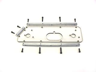 Figure 1. |
| Step 2. Install 4 of the 1-1/2" spacers onto the 4-40 x 5/8 screws that were installed in the previous step. Tighten them down till the flat side is lined up with the panel and aluminum bar as shown in figure 2. Mirror for the right side. | 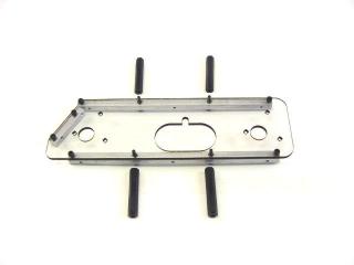 Figure 3. |
 Figure 2. |
|
| Step 3. Time to
install the motors. Be sure the use the 3mm x 6mm screws, they're the
shiny ones with the Phillips head.
12 x |
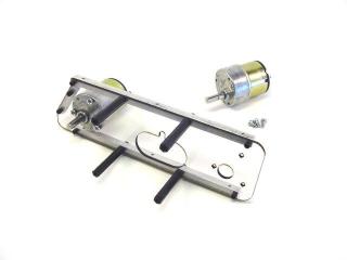 Figure 4. |
| Step 4. Solder the cap across the terminals as shown. Make sure you put the red to (+) and the black to (-). This will make wiring the speed controllers easier later on. Use at least 20 awg stranded wire and cut to a length of about 6". | 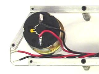 Figure 6. |
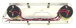 Figure 5. |
|
| Step 5. Align the
two halves of the robot upside down as shown and install the bottom panel.
Now the robot will start to take shape.
6 x |
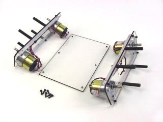 Figure 7. |
| Step 6. Install
the 1" spacers into the top panel using 6 of the 4-40 x 3/8 screws.
6 x |
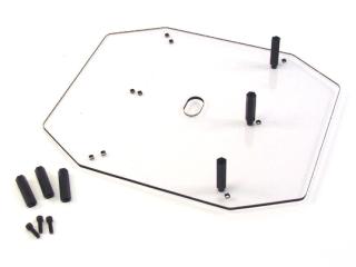 Figure 8. |
| Step 7. Install
the lid onto the robot using 6 of the 4-40 x 3/8 screws.
6 x |
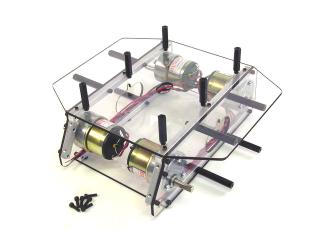 Figure 9. |
| Step 8. Install
the top onto the robot using 6 of the 4-40 x 3/8 screws.
6 x |
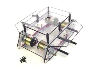 Figure 10. |
| Step 9. Install the hubs. First put the set screw into the hub. Tighten the set screw so that it just touches the flat of the motor shaft. Then push the hub down on the shaft as far as it will go, and then torque it down tight. | 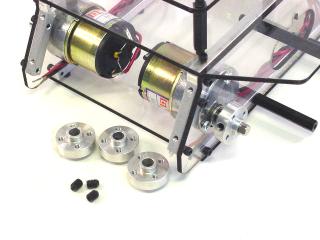 Figure 11. |
| Step 10. Install
the wheels onto the hubs using 2 of the 5-40 x 3/8 screws per wheel.
8 x |
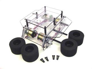 Figure 12. |
| Step 11. Install
the front scoop mount plate as shown. Use 4 of the 4-40 x 3/8 screws.
Depending on how you configure your scoop you may need to reinforce this,
or make another from aluminum using this as a template.
4 x |
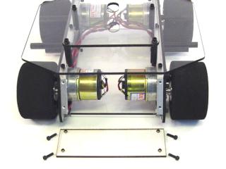 Figure 13. |
| Step 12. Install
the fenders as shown.
8 x |
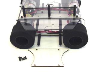 Figure 14. |
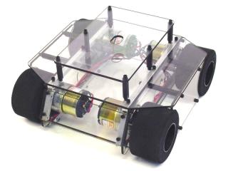
| This completes the assembly of the rolling chassis. Now you need to add your own scoop, motor drivers, sensors and microcontroller. It is still a long way from being battle ready, but it's a great start! | Figure 15. |
 8 x
8 x