
AL5C Arm Assembly Instructions Rev. 1
AL5C Arm Assembly Instructions Rev. 1
Updated October 7, 2009
Safety first! Wear eye protection and never touch a powered robot!
Note: Loctite or thread locks can be used on aluminum components. Do not use on Lexan — not necessary and may cause damage.
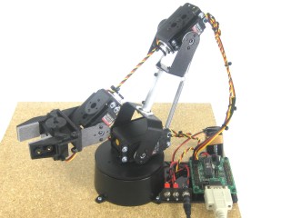
Image of complete arm.
The Lexan pieces have a protective covering that must be removed before assembly. The laser cut melts the covering into the cut edge. Gently scrape the cut edge with a flat blade screwdriver to lift and peel the covering off. On smaller pieces, use duct tape after scraping. For further information see this page.
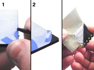 Lexan Preparation.
Attach two tubing connector hubs to the "C" and large "C" brackets using four 2-56 x .250 screws and 2-56 nuts.
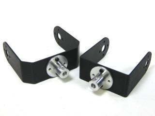 Figure 1.
Connect the hubs to the 2.25" tube using two 4-40 x .250" screws.
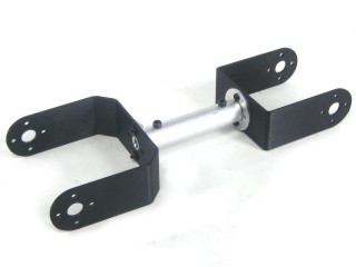 Figure 2.
Install the mechanical dampening panels as shown using four #2 tapping screws.
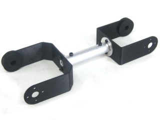 Figure 3.
Insert the 4-40 x .5" Phillips head screw through the hole in the multi-purpose bracket as shown. Secure with a steel nut.
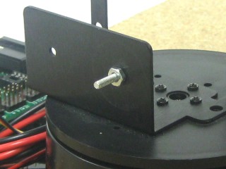 Figure 4.
Slide the large "C" bracket end over the screw and secure with a nylon insert lock nut. Start loose — tighten only if the arm wobbles. Caution: do not over-tighten! If dampeners are too tight the servo WILL heat up and CAN be damaged!
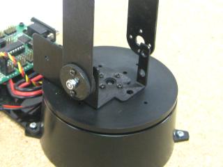 Figure 5.
Replace the black servo horn on the HS-755HB mega servo with the round nylon servo horn. Remove the screw without rotating the horn, pull it off, press the nylon horn in place as shown, and replace the screw. The arrows point to the screw holes you will use.
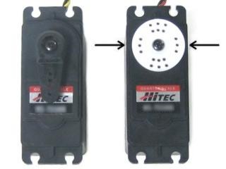 Figure 6.
Attach the HS-755HB servo to the base bracket using the 3mm hardware per the diagram below. Use two #2 x 1/4" tapping screws to secure the bracket to the servo horn. Route wires underneath the servo. Plug into channel 1 on the SSC-32. Rotate to an extreme and use a wire tie to take up cable slack.
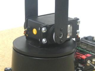 Figure 7.
Attach two tubing connector hubs to the short side of the "L" brackets using four 2-56 x .250 screws and 2-56 nuts.