
BRAT Biped Assembly Guide
Biped BRAT Assembly Guide
Updated May 2015
Safety first! Wear eye protection and never touch a powered robot!
This guide applies to: BRATCB, BRATCC, BRATCBU, BRATCCU, BRATCFB, BRATCA (Bot Board 2, BotBoarduino, SSC-32, SSC-32U variants).
Important! Build a right leg following the right-side figures and a left leg following the left-side figures. After the legs are constructed, images will no longer be split.
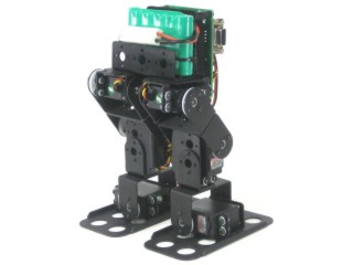
Completed robot.
Attach a multi-purpose bracket to each foot as shown, using three 2-56 x .125" screws and 2-56 nuts per foot (6 total).
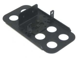 Figure 1 (Left Leg).
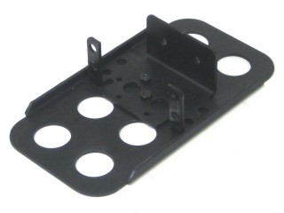 Figure 1 (Right Leg).
Attach the "L" bracket to a short "C" bracket as shown using two 2-56 x .250" screws and 2-56 nuts each (4 total).
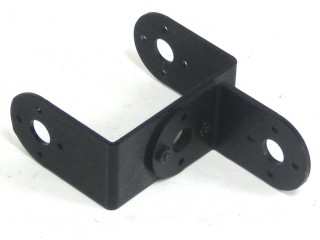 Figure 2 (Left Leg).
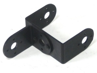 Figure 2 (Right Leg).
Attach a multi-purpose bracket to the "L" bracket as shown using two 2-56 x .250" screws and 2-56 nuts each (4 total).
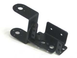 Figure 3 (Left Leg).
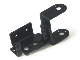 Figure 3 (Right Leg).
Attach the assembly from Step 3 to the multi-purpose bracket on the foot. Refer to Figure 4-1 for ball bearing detail.
Figure 4-1 — Ball bearing detail.
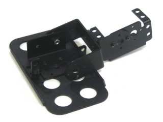 Figure 4 (Left Leg).
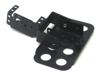 Figure 4 (Right Leg).
Connect two short "C" brackets as shown using two 2-56 x .250" screws and 2-56 nuts each (4 total).
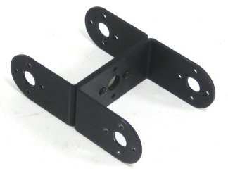 Figure 5 (Left Leg).
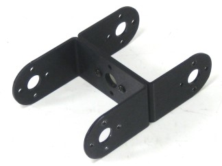 Figure 5 (Right Leg).
Attach the "C" brackets to the leg assemblies as shown. Refer to Figure 6-1 for ball bearing detail.
Figure 6-1 — Ball bearing detail.
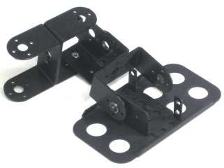 Figure 6 (Left Leg).
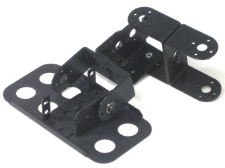 Figure 6 (Right Leg).
Attach a multi-purpose bracket to the "C" bracket as shown. Refer to Figure 7-1 for ball bearing detail.
Figure 7-1 — Ball bearing detail.
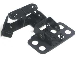 Figure 7 (Left Leg).
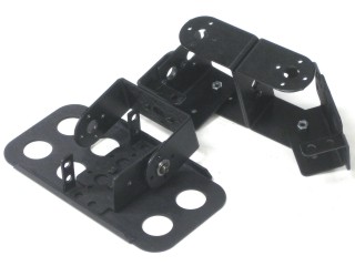 Figure 7 (Right Leg).
Attach the leg assembly from Step 7 to the 3" U-Channel as shown, using three 2-56 x .250" screws and 2-56 nuts on each side (6 total per side).
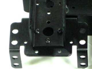 Figure 8 (Left Leg).
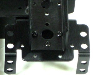 Figure 8 (Right Leg).
Your assembly should look like Figure 9. Note the robot is shown face down. From this point, a single image per step is used.
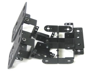 Figure 9.
Install the two ankle servos as shown using the included 3mm hardware and two #2 tapping screws per servo (4 total). Note: servos may be slightly off-centre — this will be corrected in software later.
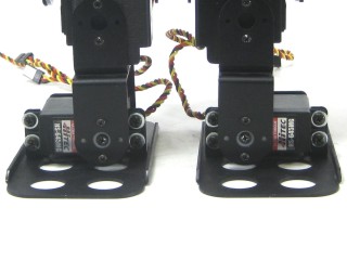 Figure 10.
Install the knee and hip servos as shown using the #2 tapping screws and the hole diagram (8 total).
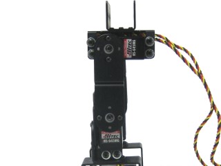 Figure 11.
SSC-32 / SSC-32U / no PS2 — Step 12a
Attach the 3/4" standoffs to the electronics carrier using four 4-40 x 1/4" hex socket screws.
BotBoarduino / Bot Board 2 with PS2 receiver — Step 12b
Attach the 1/2" standoffs instead. Note: some images below still show 3/4" spacers — your build will have 1/2". Mount the PS2 receiver to the Lexan plate using the four screws provided.
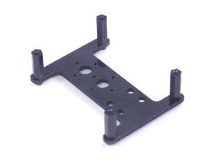 Figure 12a (SSC-32 / SSC-32U).
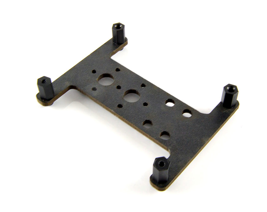 Figure 12b (with PS2 plate).
Attach the 5/16" standoffs to the U-Channel as shown using two 2-56 x 1/4" screws.
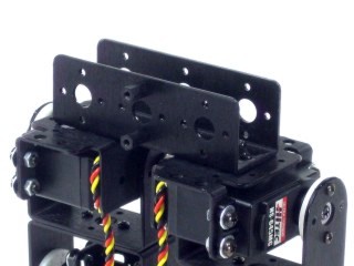 Figure 13.
Attach the electronics carrier assembly as shown using two 2-56 x 1/4" screws.
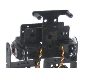 Figure 14.
To prevent wires from tangling, secure them as shown using wire ties (not included). Make sure the ankle servo is in the position shown when securing the wires to ensure full range of motion.
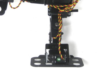 Figure 15.
Attach the battery power switch to the electronics carrier as shown. Tape, tie-wraps, or similar methods are suggested.
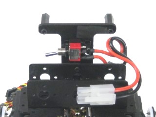 Figure 16.
SSC-32 / SSC-32U / Bot Board 2 — Step 17a
Install the board using four 4-40 x 1/4" screws. Orient it with the screw terminals at the bottom. If using a Bot Board II, install the BASIC Atom Pro 28 chip in the orientation shown. If using the optional PS2 mounting plate, use 1" M/F standoffs instead.
BotBoarduino — Step 17b
Install the BotBoarduino using four 4-40 x 1/4" screws, with the USB connector and screw terminals facing upward. If using the optional PS2 plate, use 1" M/F standoffs instead.
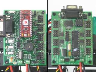 Figure 17a (Bot Board 2 / SSC-32 / SSC-32U).
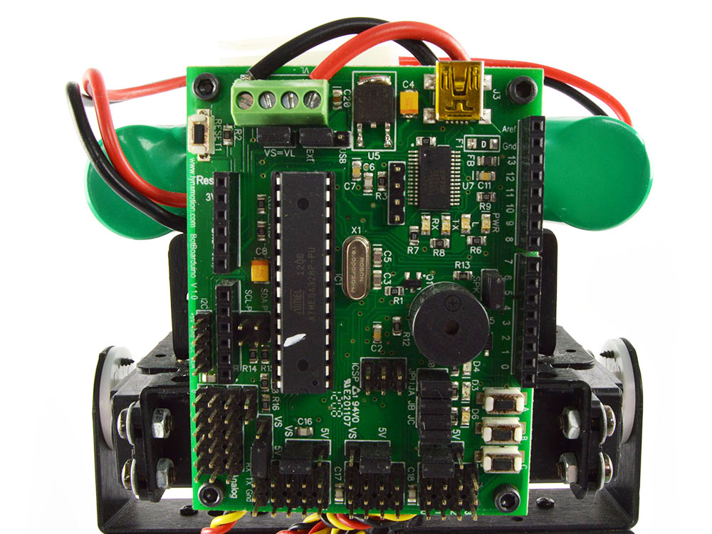 Figure 17b (BotBoarduino).
Use a ~2mm flat blade screwdriver to open the terminal (rotate until you see it open downward). Twist the wire strands by hand before inserting. Ensure no stray wire strands touch between terminals — this causes a short and can discharge the battery rapidly, generating heat and possibly fire.
DOUBLE CHECK polarity: red wire to (+), black wire to (−). Reversed polarity will damage the servos and board.
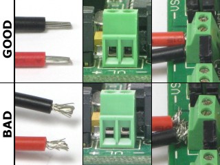 Figure 18 (top = open, bottom = closed).
SSC-32 / SSC-32U / Bot Board 2 — Step 19a
Connect the battery harness to VS1 on the SSC-32/32U, or VS on the Bot Board II. Red = (+), black = (−). Leave the VL=VS jumper and VS1=VS2 jumpers in place. Connect servos per Table 19a. Note: pin 10 for Right Hip on Bot Board II is not a typo — pin 9 is reserved for the speaker.
BotBoarduino — Step 19b
Connect the harness to VS or VL on the BotBoarduino. Leave the VL=VS jumper in place. Red = (+), black = (−). Connect servos per Table 19b.
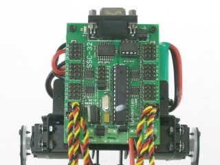 Figure 19a (SSC-32).
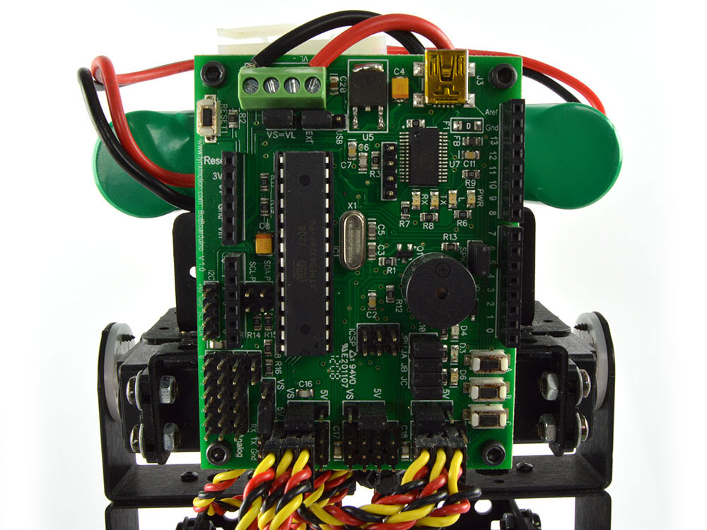 Figure 19b (BotBoarduino).
Servo Channels — SSC-32 / 32U / Bot Board 2 (Table 19a)
| SSC-32 / 32U I/O | Servo | Bot Board II I/O |
|---|---|---|
| 00 | Right Ankle | 07 |
| 01 | Right Knee | 08 |
| 02 | Right Hip | 10 |
| 16 | Left Ankle | 04 |
| 17 | Left Knee | 05 |
| 18 | Left Hip | 06 |
Servo Channels — BotBoarduino (Table 19b)
| BotBoarduino Digital I/O | Servo |
|---|---|
| 10 | Right Ankle |
| 11 | Right Knee |
| 12 | Right Hip |
| 02 | Left Ankle |
| 03 | Left Knee |
| 04 | Left Hip |
6V 1600mAh NiMh — Step 20a
This battery fits inside the U-Channel. Secure it in place with zip ties.
6V 2800mAh NiMh or other 6V battery — Step 20b
Place the battery on top of the U-Channel and secure with zip ties.
Next steps by controller type:
- SSC-32 + Sequencer: Sequencer tutorial
- SSC-32U + FlowBotics Studio: Install and open FlowBotics Studio and follow the instructions.
- Bot Board II: Autonomous, Water-Bottle Kicking, or PS2 tutorial
- BotBoarduino: BRAT + BotBoarduino + PS2 tutorial
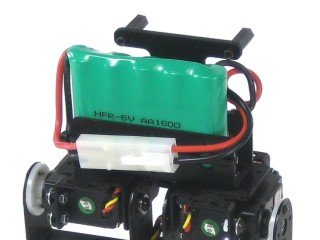 Figure 20a (1600mAh battery).
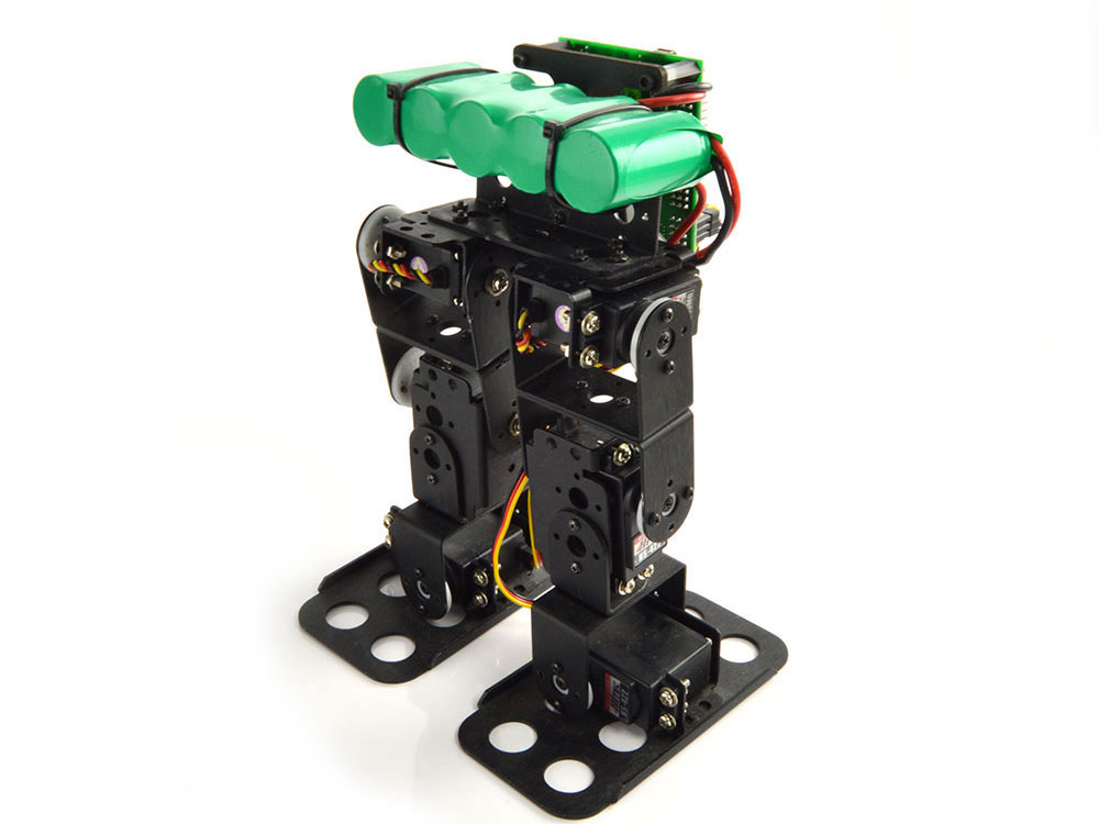 Figure 20b (2800mAh battery).
If you have the optional PS2 receiver and mounting plate, Figure 21 shows the completed robot with this attachment. Mount the PS2 Lexan + receiver assembly using four 4-40 x 1/4" screws. Note: the PS2 receiver is only compatible with the Bot Board 2 and BotBoarduino versions.
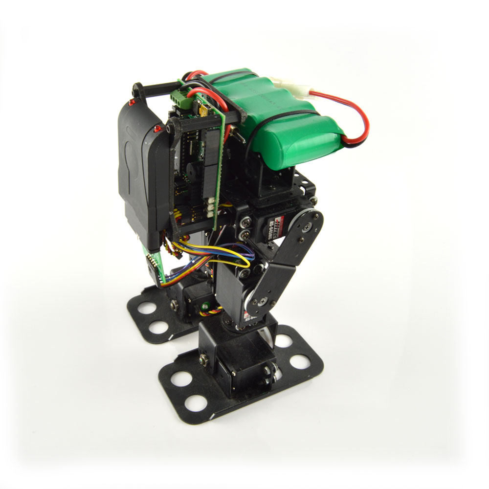 Figure 21 (with PS2 receiver).