LSS-2MC Board

Table of Contents
- Description
- Features
- Specifications
- Schematic
- Communication
- Pinout
- Wiring & Power Options
- Dimensions & Mounting
Description
The Lynxmotion LSS-2MC ("Lynxmotion Smart Servo To Motor Controller") module was designed as a multi-purpose, Arduino programmable board intended to "bridge the gap" between a Lynxmotion Smart Servo (LSS) serial bus and one or two electromechanical devices operating on PWM input like brushed DC motors (used to rotate fans, pumps or wheels for example), or LEDs. The onboard motor controller chip also allows for control of one bipolar stepper motor using all four pins. Although a default program is included when shipped, it can be re-programmed using the standard Arduino IDE software to communicate with the onboard motor controller acting as a standard Arduino board.
Features
- Dual 1.2A H-Bridge motor driver ()
- USB Type-C connector
- 2x LSS connectors allow for daisy chaining
- Input / Output A3 pin under the USB Type-C (Unpopulated / Solder pads only)
- LED (red): Tx-Rx USB serial activity
- LED (green): Power LED (PWR)
- Arduino Nano bootloader installed & Arduino IDE compatible
- Lynxmotion Smart Servo (LSS) mounting pattern
- Same form factor as the LSS - Power Hub / LSS-2IO Board / LSS-5VR Board
Specifications
- Microcontroller: ATMega328P
- USB-to-Serial IC: CH340E (Driver Download)
- Logic voltage: 5V
- Analog voltage: 5V
- 5V maximum current: 200mA
- Number of analog pins: 1 (A3)
- Input voltage via LSS connector: 6V-12V
- Maximum rated current through LSS connectors: 2A
Schematic
The complete schematic can be downloaded .
Communication
Using the LSS-2MC with its Lss2MC example code requires that the user understand the Protocol which is available HERE.
The code is available on GitHub and in the AlternativeLSS library through the Arduino IDE library manager.
Internal Serial Connection
The board is effectively a "peripheral". In order to respond to LSS commands, it needs to be running appropriate code, or the default Lss2MC Arduino sample program.
Pinout is as follows:
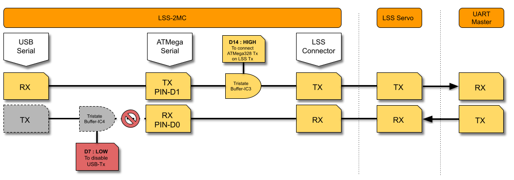
- ATMega328P's Tx pin (D1) is connected to the LSS Tx line through a tri-state buffer (IC3) that can be enabled or disabled with pin D14.
- ATMega328P's Rx pin (D0) is connected to the LSS Rx line.
Therefore data that is sent from an external UART device will be received on the LSS Rx line and the ATMega328P Rx pin. The LSS-2MC USB-to-Serial IC Tx is connected to the ATMega328P Rx (pin D0) through another tri-state buffer (IC4) that can be enabled/disabled with pin D7. The Lss2MC Arduino code inherently takes care of managing the pins D14 and D7 as follows :
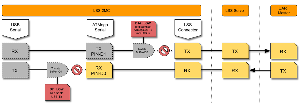
- D7 is LOW: to disconnect 2MC USB-to-Serial IC Tx from ATMega328P Rx (pin D0) allowing the ATMega328P to receive data from the UART controller device as 2MC USB-to-Serial IC Tx is HIGH when 2MC is powered.
- D14 is HIGH: when the 2MC Board is sending data on the LSS Tx line to an external UART device Rx pin. LSS Tx line is asserted to the 2MC Tx pin :
- D14 is LOW: when the 2IO Board is not sending data on the LSS Tx line. The 2IO frees up the LSS Tx line to avoid bus congestion (when 2 devices sends data at the same time) :
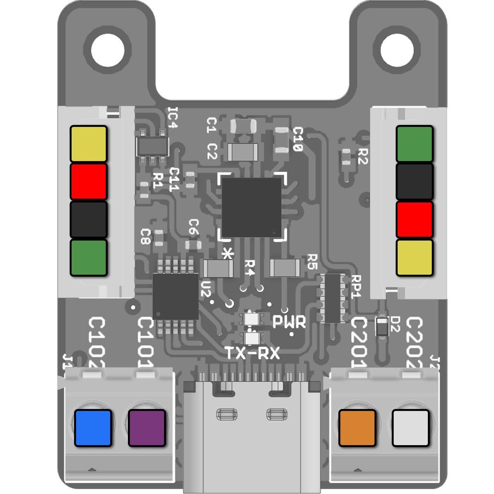
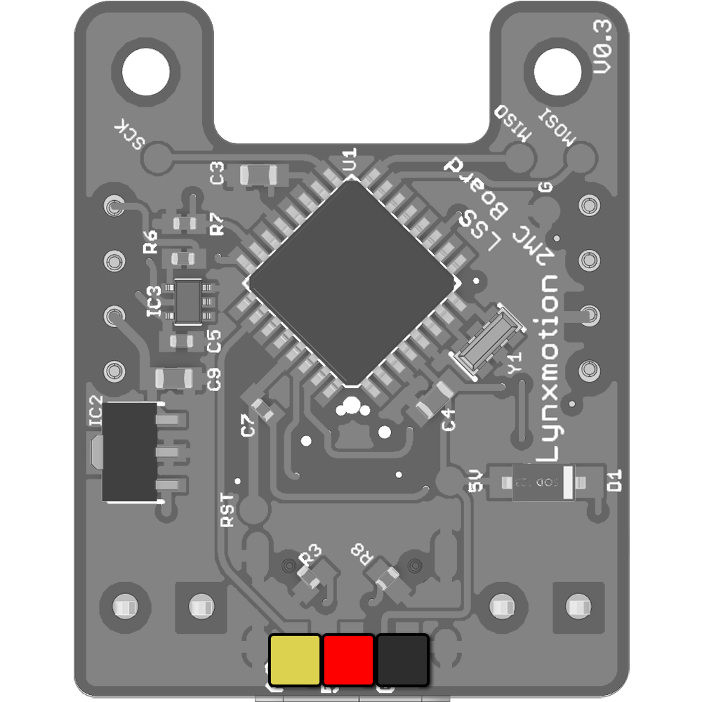
Pinout
| Top External Pins | ||
|  | Vin: Input voltage supplied by LSS bus (6V to ~12V) |
 | Ground (G): Common ground | |
 | LSS Rx | |
 | LSS Tx | |
 | H-Bridge Output #1 | |
 | H-Bridge Output #2 | |
 | H-Bridge Output #3 | |
 | H-Bridge Output #4 | |
| Bottom Solder Pins (Optional) | ||
| | Pin A3: Analog input 3 |
| 5V Out: Low current output for sensor when used with A3 | |
| Ground (G): Common ground | |
| Internal Pins / Connections | ||
| Pin D14: Controls the tri-state buffer (IC3) on the ATMega328P Tx serial line (pulled-down) | ||
| Pin D7: Controls the tri-state buffer (IC4) on CH340E Tx / ATMega328P Rx serial line (pulled-up) | ||
| Pin D9: H-Bridge Input #1 | ||
| Pin D10: H-Bridge Input #2 | ||
| Pin D3: H-Bridge Input #3 | ||
| Pin D11: H-Bridge Input #4 | ||
| Pins A4: H-Bridge i2c (SDA = A4) | ||
| Pin D2: H-Bridge NSleep (set high to enable) | ||
| Pin D8: H-Bridge NFault | ||
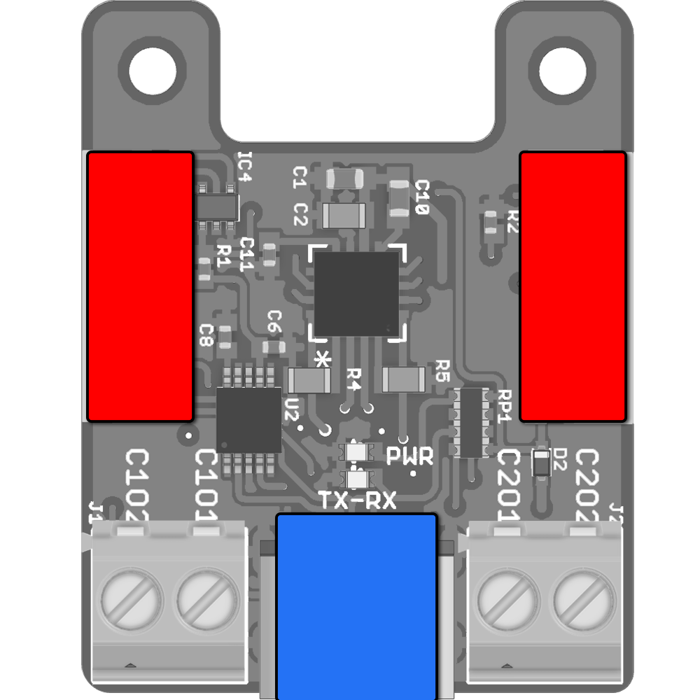
Wiring & Power Options
| Power | ||
| | LSS Connectors: The board is meant to be powered from ONE of the two LSS connectors. Vin will supply the two on-board 5V regulators (logic and Vout) and to the Lynxmotion Smart Servos connected on the bus. Power will also be supplied to the h-bridge at the same voltage as the bus voltage. Refer to LSS Voltage rating in LSS - Specifications |
| USB: Connecting only the USB will only provide voltage to the logic. It won't power the h-bridge chip. | |
| **NOTE:** USB and Vin power source are isolated and there are no issues connecting both a USB and a powered LSS bus at the same time | ||
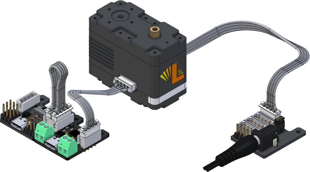
| Sample Wiring / Use | |
|
|
LSS-2MC on a bus, powered by an LSS-ADA Lynxmotion Smart Servo is optional | LSS-2MC on a bus, powered by an LSS-HUB Lynxmotion Smart Servo and LSS-2IO are optional |

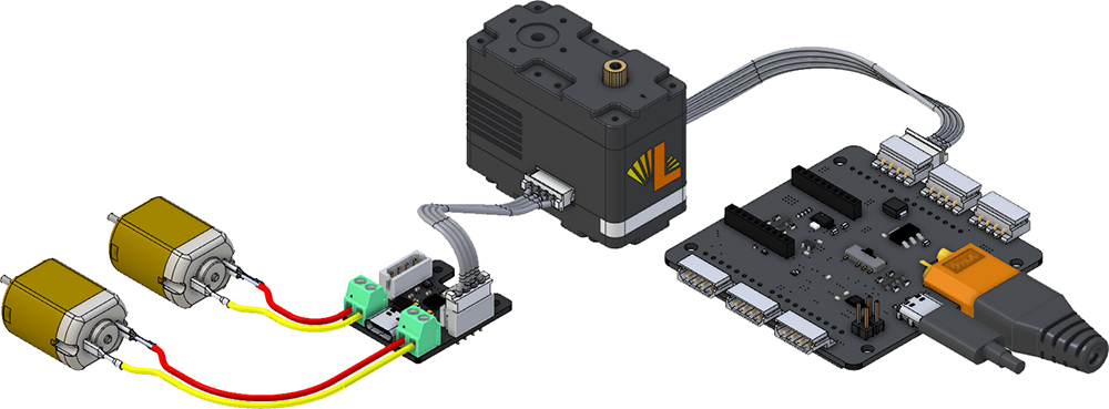
Dual H-Bridge (DC Motors)
| Sample Wiring / Use |
|
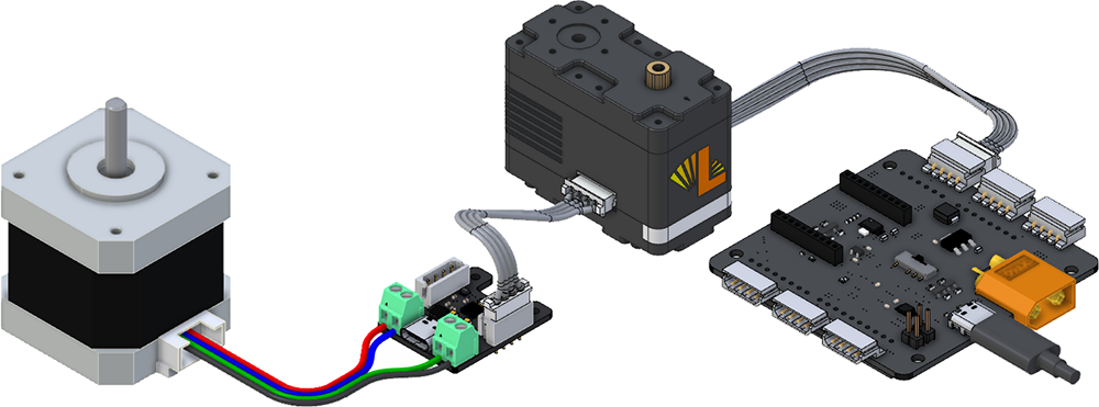
Bipolar Stepper Motor
| Sample Wiring / Use |
|
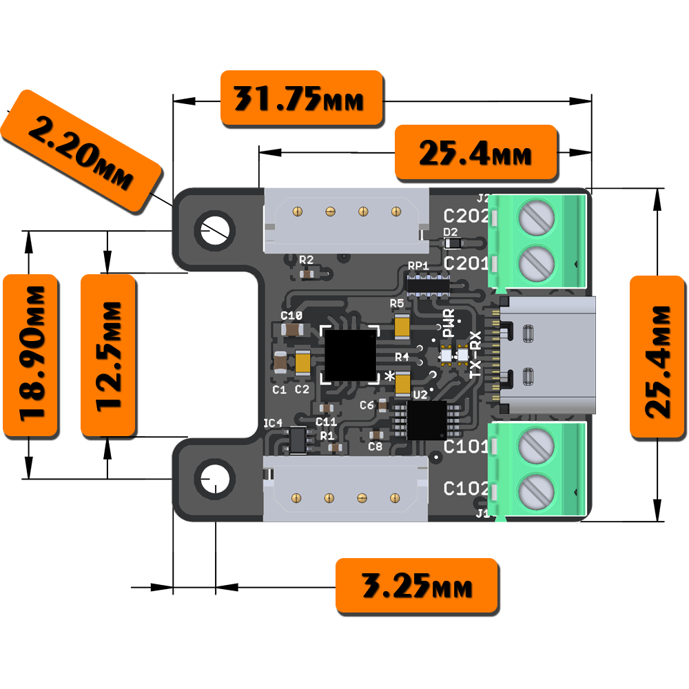
Dimensions & Mounting
|  |