
LSS - 2MC Board
Version 43.1 by Eric Nantel on 2021/04/07 14:37
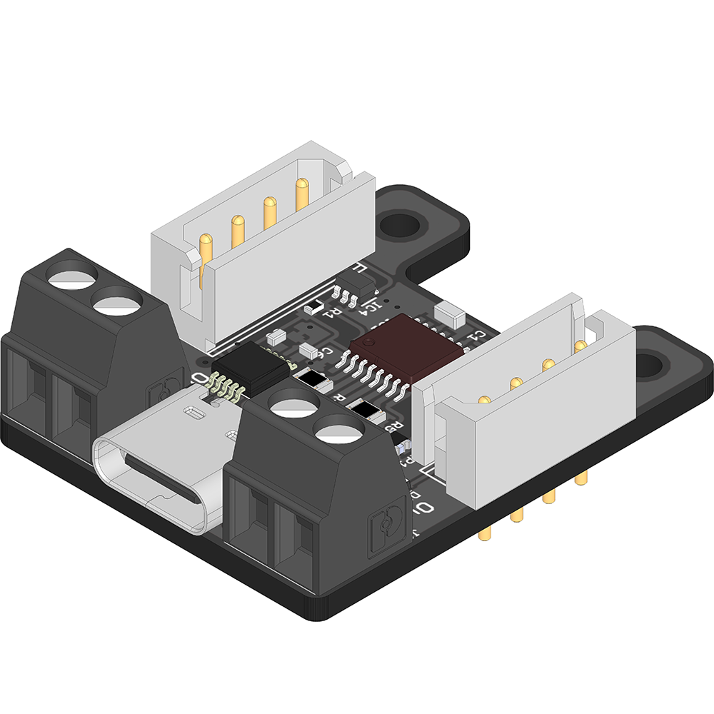

Table of Contents
Description
Lorren Ipsum
Features
- Dual H-Bridge motor driver (DRV8847SPWR)
- USB Type-C connector
- 2x LSS connectors allow for daisy chaining
- Unpopulated A3 pin under the USB Type-C
- LED (red): Tx-Rx USB serial activity (Tx & Rx)
- LED (green): Power LED (PWR)
- Arduino bootloader installed & Arduino IDE compatible
- Lynxmotion Smart Servo (LSS) mounting pattern
- Same form factor as the LSS - Power Hub / LSS-2IO Board / LSS-5VR Board
Specifications
- Microcontroller: ATMega328P
- USB-to-Serial IC: CH340E (Driver Download)
- Logic voltage: 5V
- Analog voltage: 5V
- 5V maximum current: 200mA
- Number of analog pins: 1
- Input voltage via LSS connector: 6V-12V
- Maximum rated current through LSS connectors: 2A
- Default baud rate in 2MC mode (with LSS-2IO Arduino program pre-loaded): 115200
Pinout
| Top External Pins | ||
|  | Vin: Input voltage supplied by LSS bus (6V to ~12V) |
 | Ground (G): Common ground | |
 | LSS Rx | |
 | LSS Tx | |
 | H-Bridge Output #1 | |
 | H-Bridge Output #2 | |
 | H-Bridge Output #3 | |
 | H-Bridge Output #4 | |
| Bottom External Pins | ||
| | Pin A3: Solder pad only |
| 5V Out: Low current output for sensor when used with A3 | |
| Ground (G): Common ground | |
| Internal Pins | ||
| Pin D14: Controls the tri-state buffer (IC3) on the ATMega328P Tx serial line (pulled-down) | ||
| Pin D7: Controls the tri-state buffer (IC4) on CH340E Tx / ATMega328P Rx serial line (pulled-up) | ||
| H-Bridge Input #1: Arduino D9 pin | ||
| H-Bridge Input #2: Arduino D10 pin | ||
| H-Bridge Input #3: Arduino D3 pin | ||
| H-Bridge Input #4: Arduino D11 pin | ||
| H-Bridge i2c: SDA/A4 & SCL/A5 | ||
| H-Bridge NSleep: Arduino D2 high to enable | ||
| H-Bridge NFault: Arduino D8 | ||


Power
| | LSS Connectors: The board is meant to be powered from ONE of the two LSS connectors. Vin will supply the two on-board 5V regulators (logic and Vout) and to the Lynxmotion Smart Servos connected on the bus. Refer to LSS Voltage rating in LSS - Specifications |
| USB: Connecting only the USB will only provide voltage to the logic. It won't power Vout rail nor LSS connected on the bus. | |
| **NOTE:** USB and Vin power source are isolated and there are no issues connecting both a USB and a powered LSS bus at the same time | ||

| Sample Wiring / Use | |
|
|
| LSS-2MC Powered by an LSS-ADA | LSS-2MC Powered by an LSS-HUB |


Modes
Lorren Ipsum
DC Motor Driver
Lorren Ipsum
| Sample Wiring / Use |
|

Bipolar Stepper Driver
Lorren Ipsum
| Sample Wiring / Use |
|

Pin / ID Default Assignment
The following pinout is used in the sample code so as to not interfere with any other guides or manuals. This pinout can be changed in the Arduino program.
| PIn/Device | ID | Middle Pin Supply | Notes |
| 2IO Master ID | 207 | - | RGB LED |
| A3 | 203 | 5V | Analog Pin |
| A4 | 204 | 5V | Analog Pin |
| A5 | 205 | 5V | Analog Pin |
| D9 | 209 | Not Connected | Digital Pin |
| D10 | 210 | Not Connected | Digital Pin |
| D11 | 211 | Not Connected | Digital Pin |
| To change the ID,s you can look at the "CID" command HERE | |||
Dimensions & Mounting
|  |
