LSS - Adapter Board
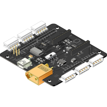
Table of Contents
- Description
- Features
- Specifications
- Communication / Control
- USB to Serial Drivers
- Pinout
- Wiring
- Power
- Configurations
- Dimensions
Description
The Lynxmotion Smart Servo (LSS) Adapter Board is an electronic board which allows for easy connection to and control of the Lynxmotion Smart Servos. The board includes a variety of features and functionality and provides power distribution via six LSS connectors. The board is ideally intended to be powered from a LiPo battery through the on-board male XT60 connector, or with a wall adapter equipped with a female XT60 connector. There are many ways to interface with this board, as described below.
Features
- Connect to and control LSS actuators via 6x connectors
- On-board Bee Socket (XBee, Bluetooth Bee WiFi Bee modules)
- Can function as a USB XBee explorer board
- Arduino shield compatible using stacking headers
- Selectable control method : USB, Arduino or XBee
- Raspberry Pi B+/2/3 mounting compatibility
- XT60 Connector for power input
- Automatic logic power selection (USB/External)
Specifications
- Continuous current per connector: 3A (max)
- Built-in USB to serial (FTDI Virtual COM Port chip)
- Built-in 5V regulator
- Built-in 3.3V regulator
- USB Mini connector
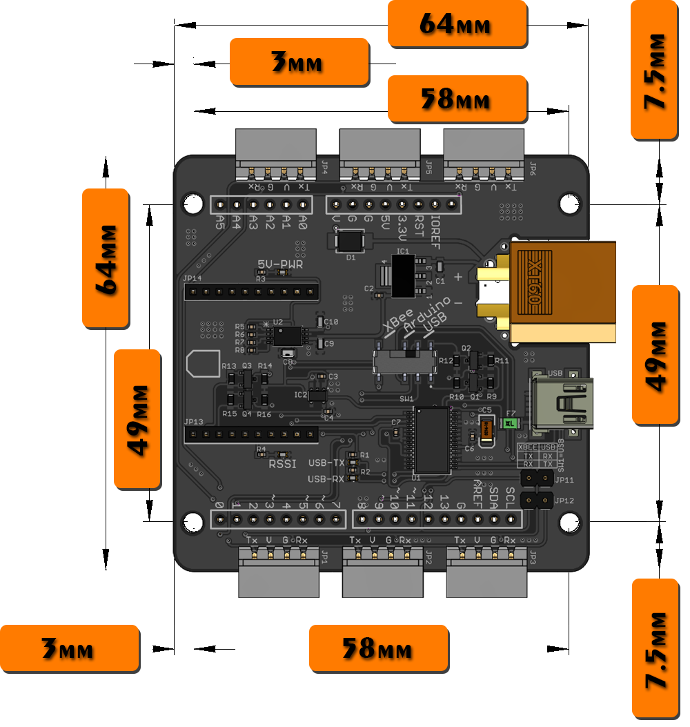
- Dimensions: 64 x 64 x 15mm
- Mounting hole diameter: 3.1mm
Communication / Control
- Mini USB: ex: computer, laptop, Raspberry Pi
- Arduino shield compatible (using M/M or extended M/F headers)
- TTL UART Microcontroller or FPGA control (5V) via Tx, Rx, GND pins
- Wireless module with XBee footprint (Bluetooth Bee, WiFi Bee etc.)
USB to Serial Drivers
The LSS Adapter uses the FT232RL FTDI chip to convert USB to UART. Most operating systems will automatically detect the FTDI chip and install the correct VCP drivers. In case this is not done automatically, VCP drivers for the FT232RL chip can be downloaded through this link (choose the VCP driver which corresponds to your operating system).
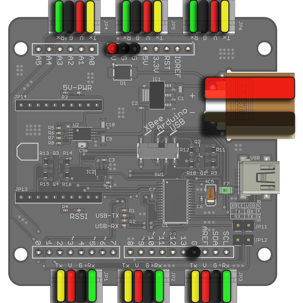
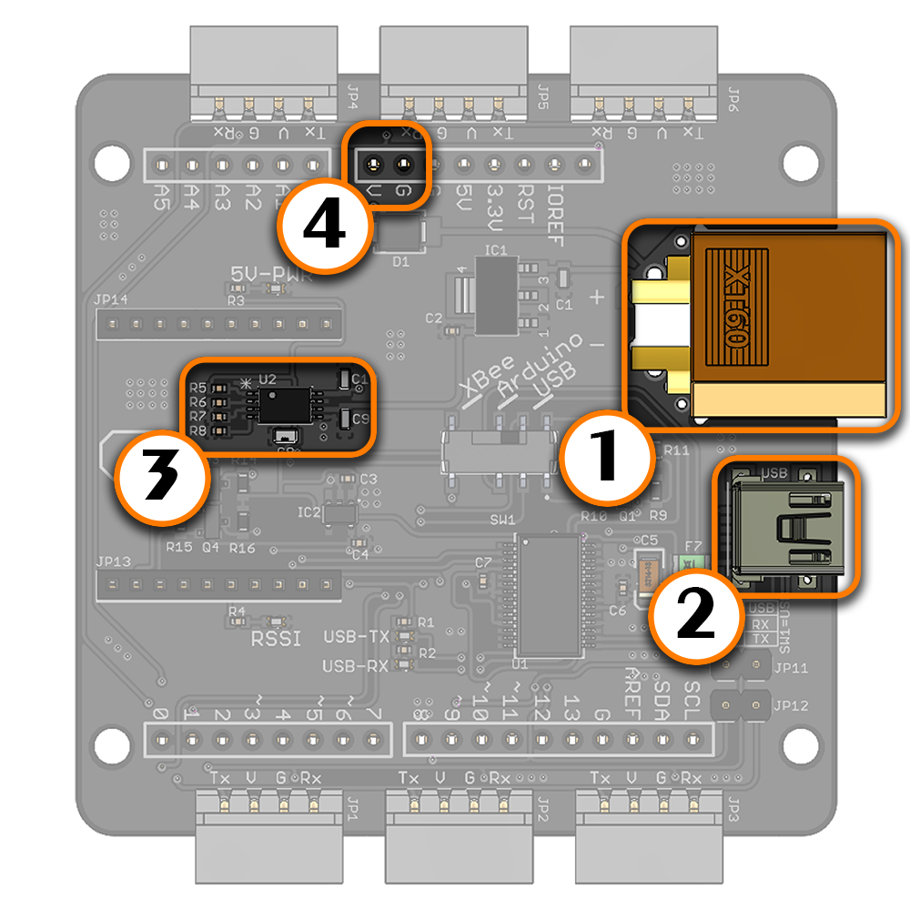
Pinout
|  | Servo Vcc pin: Refer to the Voltage section of the LSS - Specifications page to understand which voltages are meant to be connected to this pin. VCC pins on all six connectors, including the XT60 VCC and the VCC pin are connected together. |
 | Ground (GND): This pin should be connected to both the communication sources' ground, as well as that of the power source (principle of "common ground"). GND pins on all connectors, including the XT60 GND and two GND pins are corrected together. | |
 | Servo Rx pin: In serial mode, this pin should be connected to the servo's Rx serial pin. If you are using the Lynxmotion serial cables, simply plug in the servo to the LSS adapter. | |
 | Servo Tx pin: In serial mode, this pin should be connected to the servo's Tx serial pin. If you are using the Lynxmotion serial cables, simply plug in the servo to the LSS adapter. |
Wiring | |
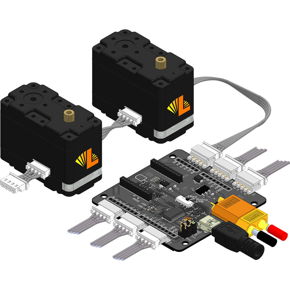
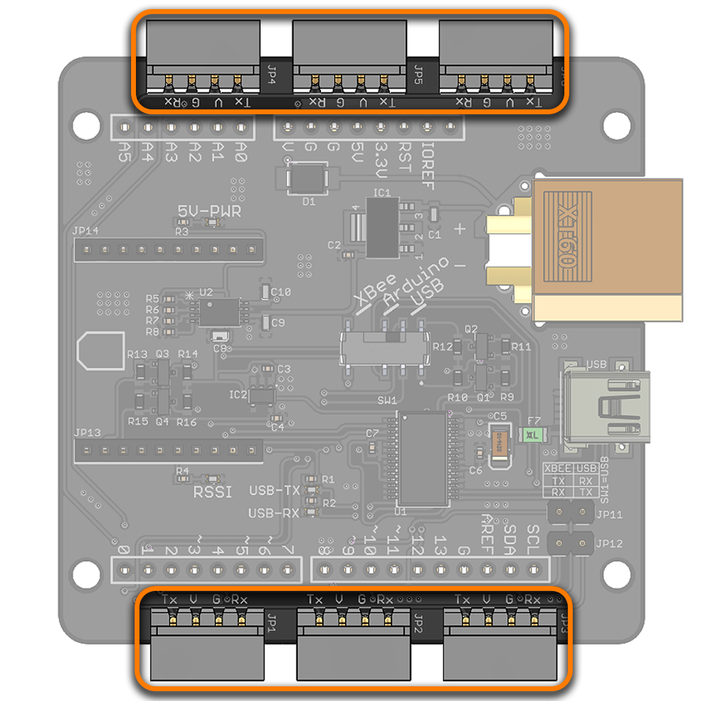
| The LSS adapter allows up to six sets of servos to be connected to the same bus and share the same power supply, which greatly simplifies wiring for more complex robots. For example, the servos used in an 18 degree of freedom hexapod robot can be split into groups of three for each leg. In order to estimate the maximum number and type(s) of servos to daisy chain to each connector on the LSS board, we suggest adding up the stall current for each servo and multiplying by 0.75 (75%). If this value is below 3A, the servos should be safe in most situations. |
Power | |
| (1) XT60 Connector for 6V-12V external power input (more information in "LSS - Electrical" section). (2) LSS servo connectors (3) Automatic switching between USB and external (VCC) power (4) VCC and GND pins FTDI The FTDI chip obtains power from either the on-board USB connector or with an external power supply through the XT60 connector. The 5V from the USB will only power the FTDI chip and the Bee socket (if a module is in place) and won't power the servos. Arduino In the case where the LSS Adapter is stacked on top of a shield-compatible Arduino microcontroller board, the Arduino can be powered from the Vin pin which is directly connected to the external supply voltage of the LSS Adapter. If the Arduino Board is powered separately via a different external power supply (ex. connected to the Arduino's barrel connector), it will NOT provide power to the LSS Adapter. The LSS adapter is designed to power the Arduino, but not vice-versa. As such, it is suggested that only ONE 6-12V power source be connected to the LSS Adapter which is used to power everything. Raspberry Pi The LSS Adapter's onboard 5V regulator does not provide enough current to power a Raspberry Pi and as such it is recommended that a Raspberry Pi be powered separately using an appropriate 5V, 2A+ USB wall adapter or 5V voltage adapter. Other MCUs The 5V or 3.3V outputs can be used to power other MCUs/Controllers. The 5V supply can provide up to 1A and the 3.3V can provide up to 500mA. |
| Servos To power the servos, an external power supply (6V to 12V) is needed (more information on the LSS - Electrical page). If both a USB and a 7V or higher external power supply are connected at the same time, the external power supply will be automatically selected / preferred in order to power the FTDI chip and Bee module. If the board is supplied with less than 7V, the 5V pins from the internal regulator may supply less than 5V and the adapter may not function properly. The external power supply can be a battery or an AC-to-DC wall adapter with the appropriate barrel to XT60 adapter. The four pins of all six connectors on the board are connected to one another. Each connector (on both the board and on each servo) can handle a maximum of 3A. The LSS Adapter is intended to provide sufficient current to all six connectors. In higher current applications, be sure to select a power supply / source which can provide the necessary current for all servos. |
Configurations
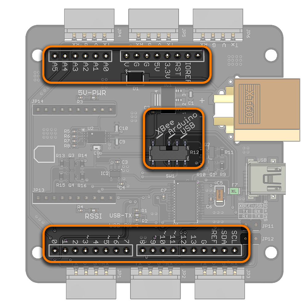
Using the LSS Adapter Board is fairly simple and user-friendly. The configuration switch on the board allows the user to select one of the following control methods
Note : A configuration can be chosen by pointing the arrow of the switch to the upper half circle of the switch or to the bottom one. For example, if USB configuration needs to be chosen, it doesn't matter which number "3" the arrow of the switch is pointing to. Both will work normally.
Arduino | |
| To use the LSS Adapter Board with an Arduino Board, the switch should be on position 1. This configuration allows controlling LSS actuators from an Arduino Board and can be used to build autonomous or semi-autonomous robots. When Arduino (position 1) is selected on the communication switch, the Arduino Rx (digital 0) is connected to the LSS actuator's Tx and Arduino Tx (digital 1) is connected to the LSS actuator's Rx. This way, the Arduino communicates with the LSS actuator through the LSS Adapter Board. By default, the Arduino is powered through the LSS Adapter Board, if the Arduino is powered separately, cut the solder jumper "Vin cut" on the bottom of the LSS Adapter Board. |
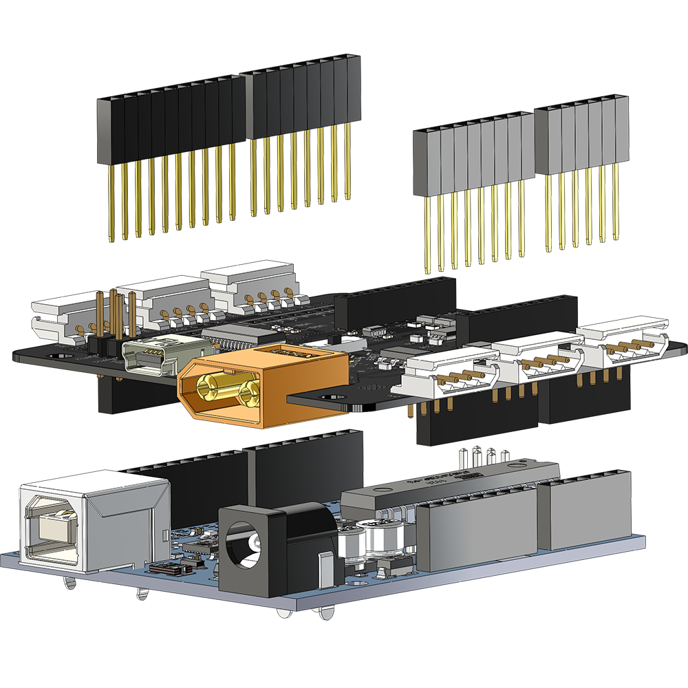
| The LSS Adapter is shield compatible. Therefore it can be stacked on top of an Arduino Board using the included Arduino stacking headers or male-to-male stacking pins. The stacking headers used are : 3 x 6 positions 0.1" (2.54mm) pitch 16mm (or higher) contact length header receptacle connectors. 1 x 8 positions 0.1" (2.54mm) pitch 16mm (or higher) contact length header receptacle connectors. |
Raspberry Pi | |
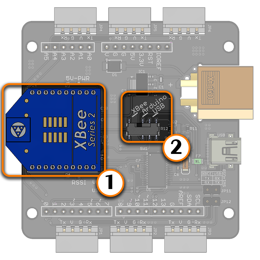
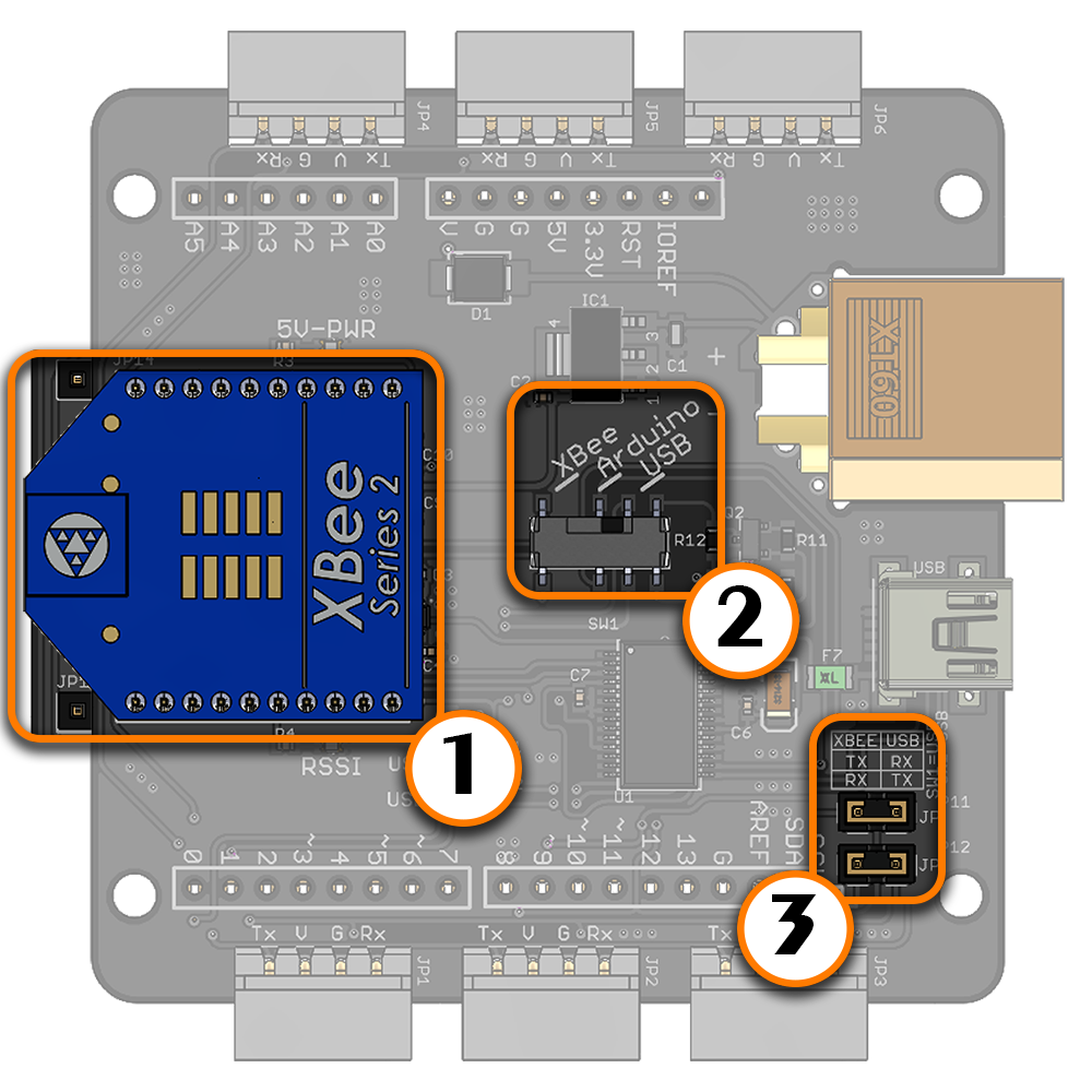
| To use the LSS Adapter Board with an XBee Module, the switch should be on position 2. This configuration allows controlling LSS actuators wirelessly with an XBee/Bluetooth Bee/Wifi Bee module. When XBee (position 2) is selected on the communication switch, the XBee Rx is connected to the LSS actuator's Tx and the XBee Tx is connected to the LSS actuator's Rx. This way, the Bee module communicates directly with the LSS actuator through the adapter. Plus, when the configuration switch is on position 2, the LSS Tx is connected to the Arduino pin 8 and the LSS Rx is connected to the Arduino pin 9 allowing to use Software Serial |
| |
XBee & Compatibles | |
|
|
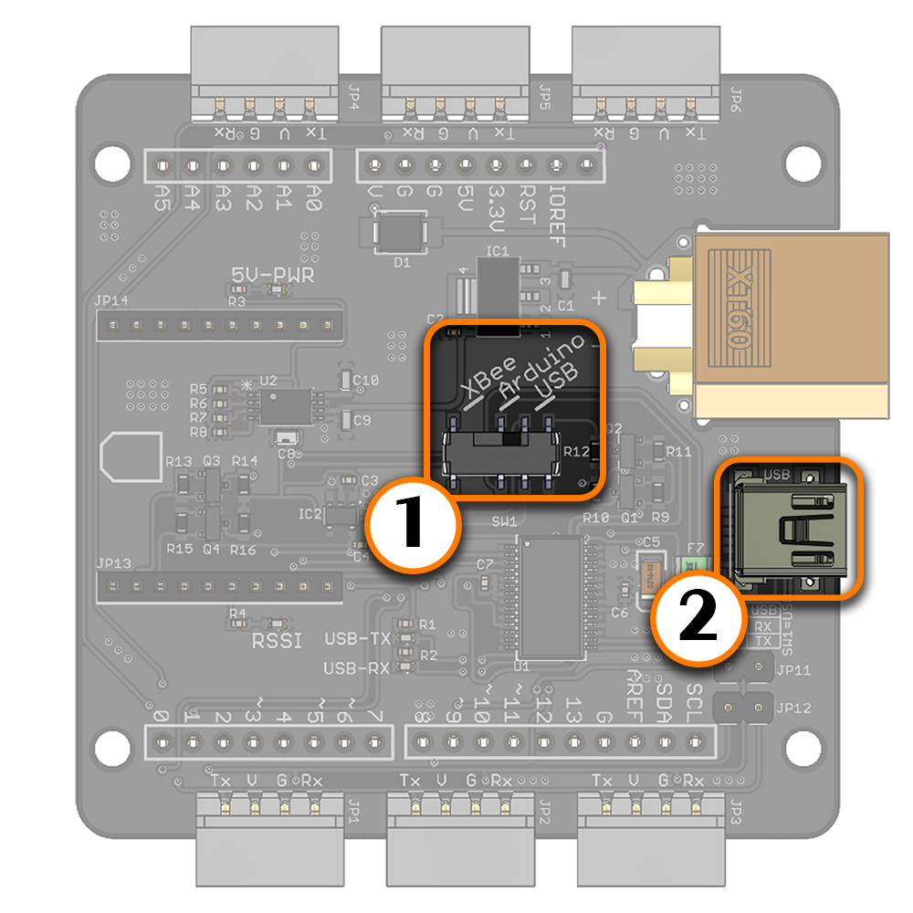
XBee Explorer | |
| The XBee Rx pin and Tx pins are connected to the Arduino's pin 8 and 9 respectively. Therefore, the LSS Adapter Board can be also used as a USB XBee explorer board to configure the XBee module through USB. To use the LSS Adapter Board as a USB XBee explorer :
|
USB Devices | |
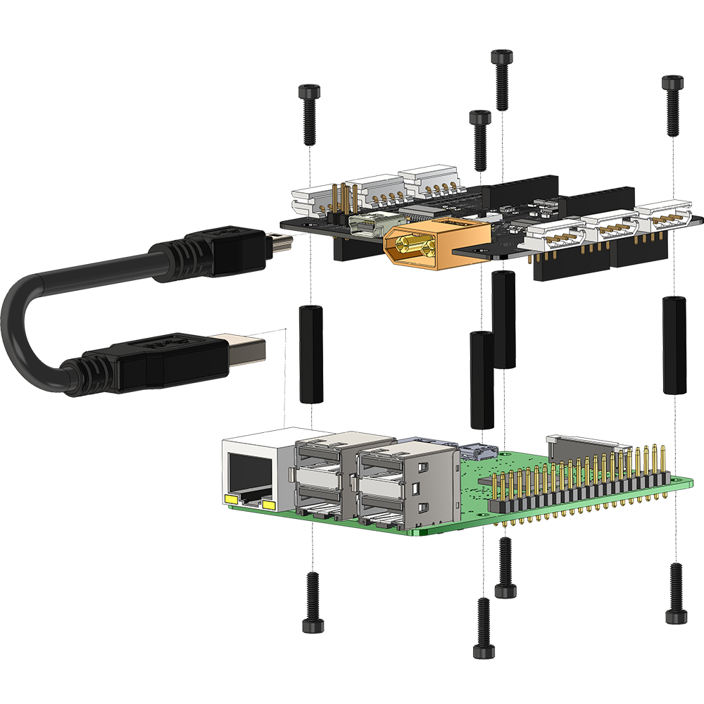
| To use the LSS Adapter Board with a Raspberry Pi or a standard computer / laptop through USB, the switch should be on position 3. This configuration allows controlling LSS actuators by sending serial commands from a computer or a Raspberry Pi via USB. The mounting holes for the LSS Adapter are compatible with the Raspberry Pi 2 / 3.
|
Dimensions
|